IPB-5000A
5. Installation and Connection
5-2
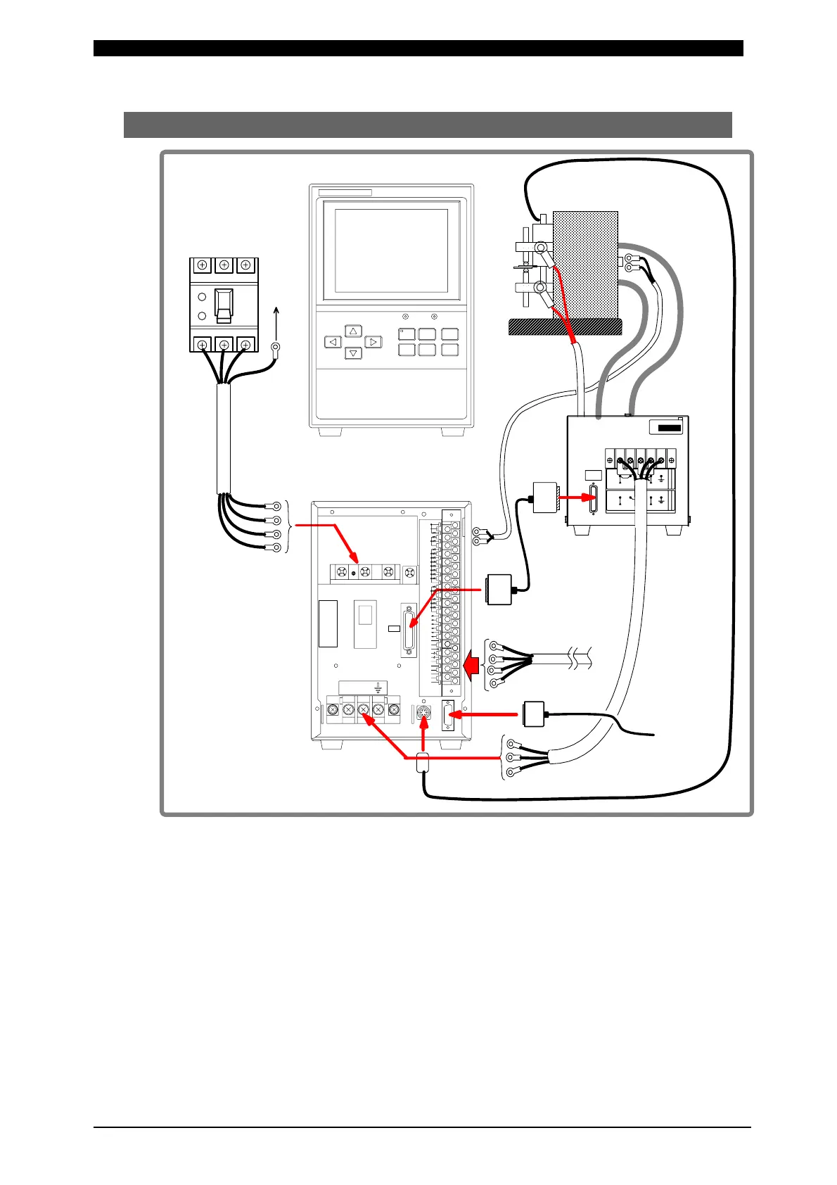
(2) Connection
Numerals of (1) to (8) in the above figure represent the order of connection
procedures in the following pages.
* 1: All items are separately sold except IPB-5000A.
* 2: The Voltage Detecting Cable is used only for Constant Voltage Control,
Constant Current/Constant Voltage Combination Control and Constant Power
Control.
* 3: Communication Cable is used only for connecting Personal Computer (PC).
* 4: Displacement Sensor is used only for the model equipped with the Sensor.
To Ground (G)
Earth
Leakage
Breaker
Input
Cable
Welding Head
IPB
-
5000A
POWERSTART
IPB-5000A
CURSOR
WELD MENU RESET
ENTER
+-
WELDING POWER SUPPLY
11 37353331292725232119171513975
383634323028262422201816141210864
STOP
1ST
2ND
COM
SCH 1
SCH 4
SCH 8
SCH16
SCH32
SCH 2
SCH64
INT.24V
EXT.COM
WELD ON/OFF
ERROR RESET
COM
COM
GOOD
NG
END
CAUTION
COUNT UP
READY
OUT COM
OUT COM
SOL 1
SOL 2
SOL COM
PRG PROTECT
39
PARITY
(WE1 STOP)
COM
W.INTERRUPT
P-00281 -001
COUNT RESET
CONTROL SIG
2
31
(OPTION1)
(OPTION2)
SOL POWER
(OPTION4)
(OPTION5)
(OPTION3)
POWER OUT
P-1463
VU
I/O
SENS
SERIAL
NO.
JAPAN
MIYACHI TE CHNOS CORP.
MADE
IN
A1
1234
インバータ出力電圧 300 V時
FOR INVERTER OUTPUT 300V
インバータ出力電圧 600V 時
FOR INVERTER OUTPUT 600V
POWER SUPPLY VOLTAGEPOWER SUPPLY VOLTAGE
AC380V~AC4 80VAC200V~AC240V
L1 L2 L3 PE
Front Panel
Rear Panel
Voltage
Detecting
Cable
*2
Secondary
Cable
Welding
Transformer
Input Terminal Block
Output
Cable
(Refer to Caution
below)
[SENS] Cable
External I/O
Signal Cable
Match the designaton
of cable with terminal
for connection
*1
Start
Cable
(1)
(6)
(5)
(4)
(3)
(2)
(7)
(8)
Communication
Cable *3
Displacement
Sensor *4
To PC