IPB-5000A
5. Installation and Connection
5-1
5. Installation and Connection
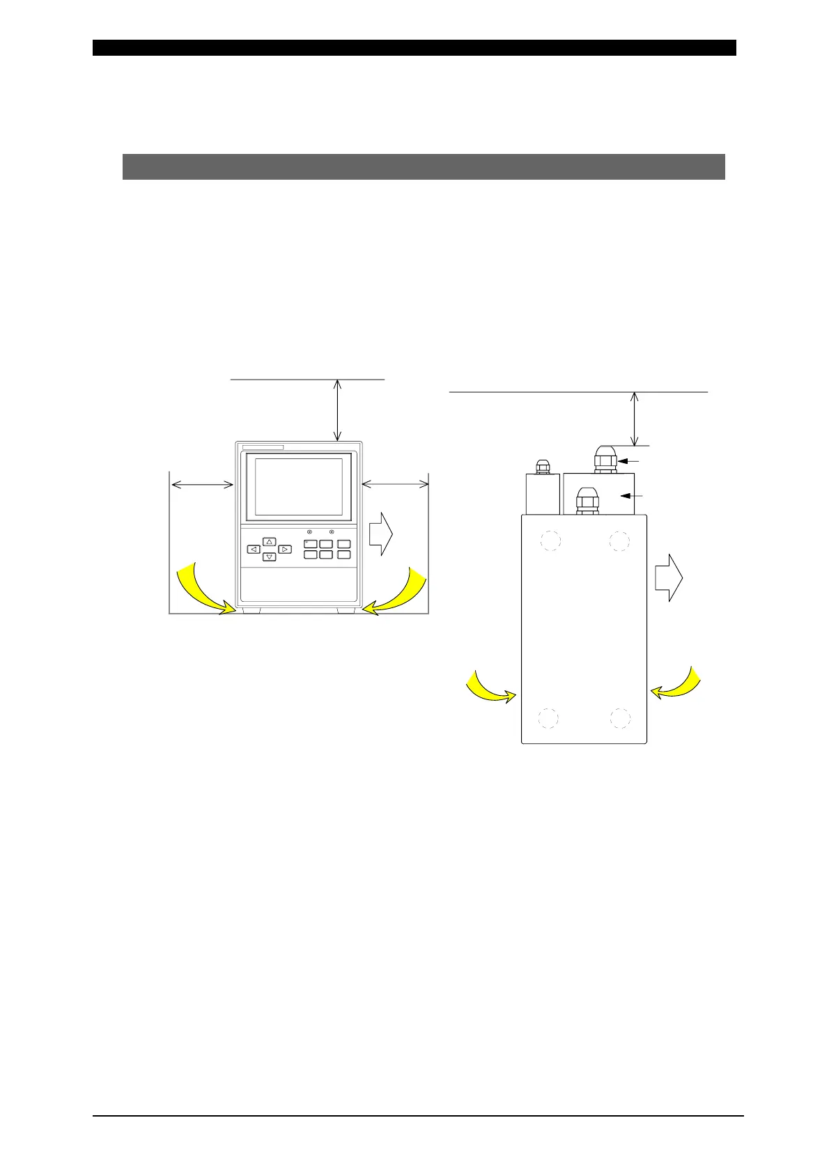
(1) Installation
When planning for the installation, allow at least the figured clearance on each
side from the wall, as referred to the figures below, for improving the effect of
heat release.
Allow at least 10cm or more from the end of the Wiring Outlet projected at the
Output Terminal Cover in the rear potion of IPB-5000A.
As IPB-5000A should be air-cooled, do not install it in a closed area.
[Front View] [Top View]
10cm or more
Outlet
POWERSTART
IPB-5000A
CURSOR
WELD MENU RESET
ENTER
+-
WELDING POWER SUPPLY
10cm or more
10cm or more
Air Inlet
Air Inlet
10cm or more
Air Inlet
Air Inlet
Outlet
(Front Portion)
(Rear Portion)
Wiring Outlet
Output Terminal
Cover