IPB-5000A
9. Time Chart
9-9
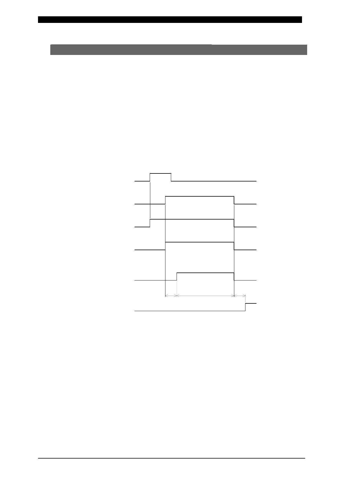
(8) Behavior in TRANS SCAN MODE
① OFF Setting
It is a setting of the case where Transformer Selector MA-650A is not used.
The behavior is the same as the one in (1) Fundamental Sequence.
Those settings mentioned below in ② through ⑥ are the ones of the case
where Transformer Selector MA-650A is used.
② ON Setting
The weld current is supplied through the transformer set at the item of
Transformer No. (TR#) in SCHEDULE Screen.
Supposing that SCHEDULE No. is 2 (SCH2) and Transformer No. is 3 (TR#3),
the time chart where the supply of weld current is started is shown as follows.
a: Transformer Changeover Time (10ms)
b: Time period for computing a monitored value
See b: Time period for computing a monitored value at
9.(1)Fundamental Sequence.
Because Transformer 3 (TR#3) is set for SCHEDULE#2 (SCH2), weld
current is supplied through the Transformer connected to Transformer 3 in
Transformer Selector MA-650A.
END Output OFF
SOL2 Output
SOL1 Output
2ND STAGE
1ST STAGE OFF
OFF
OFF
OFF
Transformer No.
ON Setting in Transformer Selector
Weld
SCH2
TR#3
a b