IPB-5000A
9. Time Chart
9-10
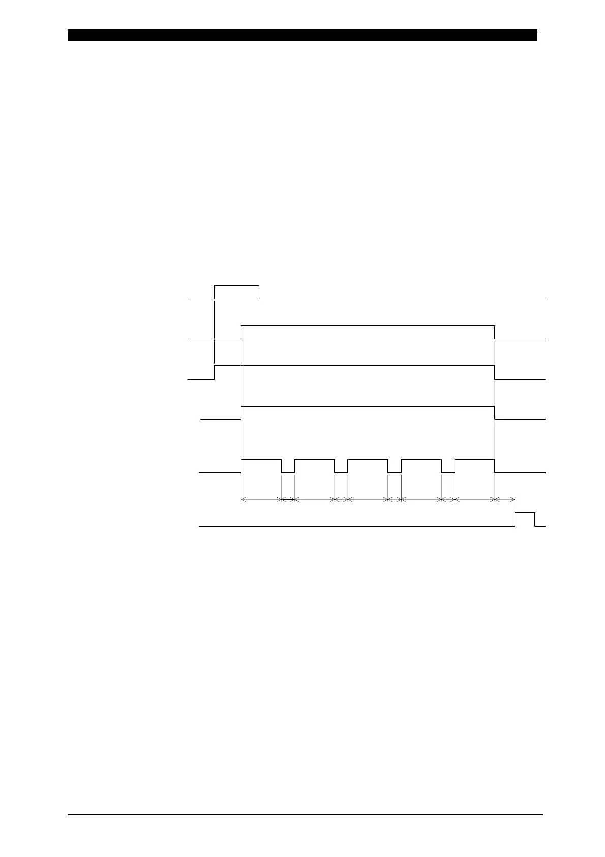
③ 1-5 Setting
Firstly, weld current is supplied on the first selected SCHEDULE No. and then
on the consecutive 5 SCHEDULE No.’s including the first selected No. in turn .
In this occasion, weld current is supplied through the transformer selected at
Transformer No. (TR#) in each SCHEDULE Screen.
That is to say, in the case that the supply of weld current is started in the
condition of SCHEDULE No.2 selected, firstly weld current is supplied on
SCHEDULE No.2, then SCHEDULE No.3, SCHEDULE No.4, SCHEDULE
No.5, lastly on SCHEDULE No.6.
For example, Supposing that SCHEDULE No. is 2 (SCH2) and Transformer No.
is 1 (TR#1), similarly SCH3-TR#4, SCH4-TR#5, SCH5-TR#2, SCH6-TR#3,
the time chart where the supply of weld current is started is shown as follows.
As Transformer 1 (TR#1) is set for the first SCHEDULE No.2 (SCH2), weld
current is firstly supplied through the transformer connected to Transformer 1
of Transformer Selector MA-650A, and then through Transformer 4,
Transformer 5, Transformer 2 and Transformer 3 in turn.
a: Monitored Value Computing Time and Transformer Changeover Time
It is the sum of b: Monitored Value Computing Time plus Transformer
Changeover Time, 10ms.
b: Monitored Value Computing Time
Changes in dependence on Monitor Value Calculation Mode
(CALCULATION MODE at 6.(9)①STATUS(1/2)Screen), Communication
Setting (COMM CONTROL and COMM SPEED at 6.(9)②STATUS(2/2)
Screen) and the type of screens as the following page.
END Output
Weld Current
SCH2
SOL2 output
SOL1 Output
2ND STAGE
1ST STAGE OFF
Transformer No.
TR#1
TR#4 TR#5 TR#2 TR#3
a
OFF
OFF
OFF
OFF
OFF
SCH3 SCH4
SCH5
SCH6
a
a
a
b
1-5 Setting in Transformer Selector