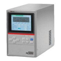
IPB-5000A
1
Table of Contents
1. Special Precautions··································································································· 1-1
(1) Safety Precautions································································································· 1-1
(2) Precautions for Handling ······················································································· 1-4
(3) Warning Labels for Safety ····················································································· 1-5
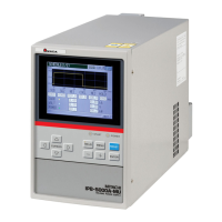
(4) Function Difference Depending on Model ····························································· 1-5
2. Features ······················································································································ 2-1
3. Packaging ··················································································································· 3-1
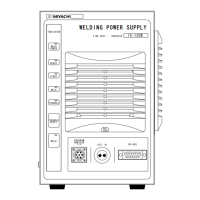
4. Name and Functions of Each Section ····································································· 4-1
(1) Front Panel ············································································································ 4-1
(2) Rear Panel ············································································································· 4-3
5. Installation and Connection······················································································ 5-1
(1) Installation·············································································································· 5-1
(2) Connection············································································································· 5-2
6. Description of Display Screens················································································ 6-1
(1) Operation Flow······································································································· 6-1
(2) MENU Screen ········································································································ 6-2
(3) SCHEDULE Screen ······························································································· 6-2
(4) MONITOR Screen·································································································· 6-6
(5) COMPARATOR Screen························································································· 6-8
(6) ENVELOPE Screen ······························································································· 6-9
(7) PRECHECK Screen······························································································· 6-13
(8) CONTROL Screen ································································································· 6-14
(9) STATUS Screen ···································································································· 6-16
① STATUS (1/2) Screen ······················································································· 6-16
② STATUS (2/2) Screen ······················································································· 6-18
③ ERROR SETTING Screen ················································································ 6-20
④ MISC Screen ····································································································· 6-20
7. Basic Operation ········································································································· 7-1
8. External Interface······································································································· 8-1
(1) Connection Diagram for External Input/Output Signals········································· 8-1
① When contacts on PLC are used as input signal ·············································· 8-1
② When NPN transistor (sink type) on PLC is used as input signal ····················· 8-2
③ When PNP transistor (source type) on PLC is used as input signal················· 8-3
④ When solenoid valves are activated by the use of an external power supply ·· 8-4
⑤ When solenoid valves are activated by the use of an internal power supply ··· 8-4
(2) External Input/Output Signals ················································································ 8-4
(3) Schedule No. and Schedule Select Terminals ······················································ 8-8
9. Time Chart ················································································································ 9-1
(1) Fundamental Sequence························································································· 9-1
(2) Determination of Weld Schedule ··········································································· 9-3
(3) Behavior of START SIG. HOLD············································································· 9-4
(4) Behavior of END SIG. TIME ·················································································· 9-5