IPB-5000A
10. External Communication Function
10-9
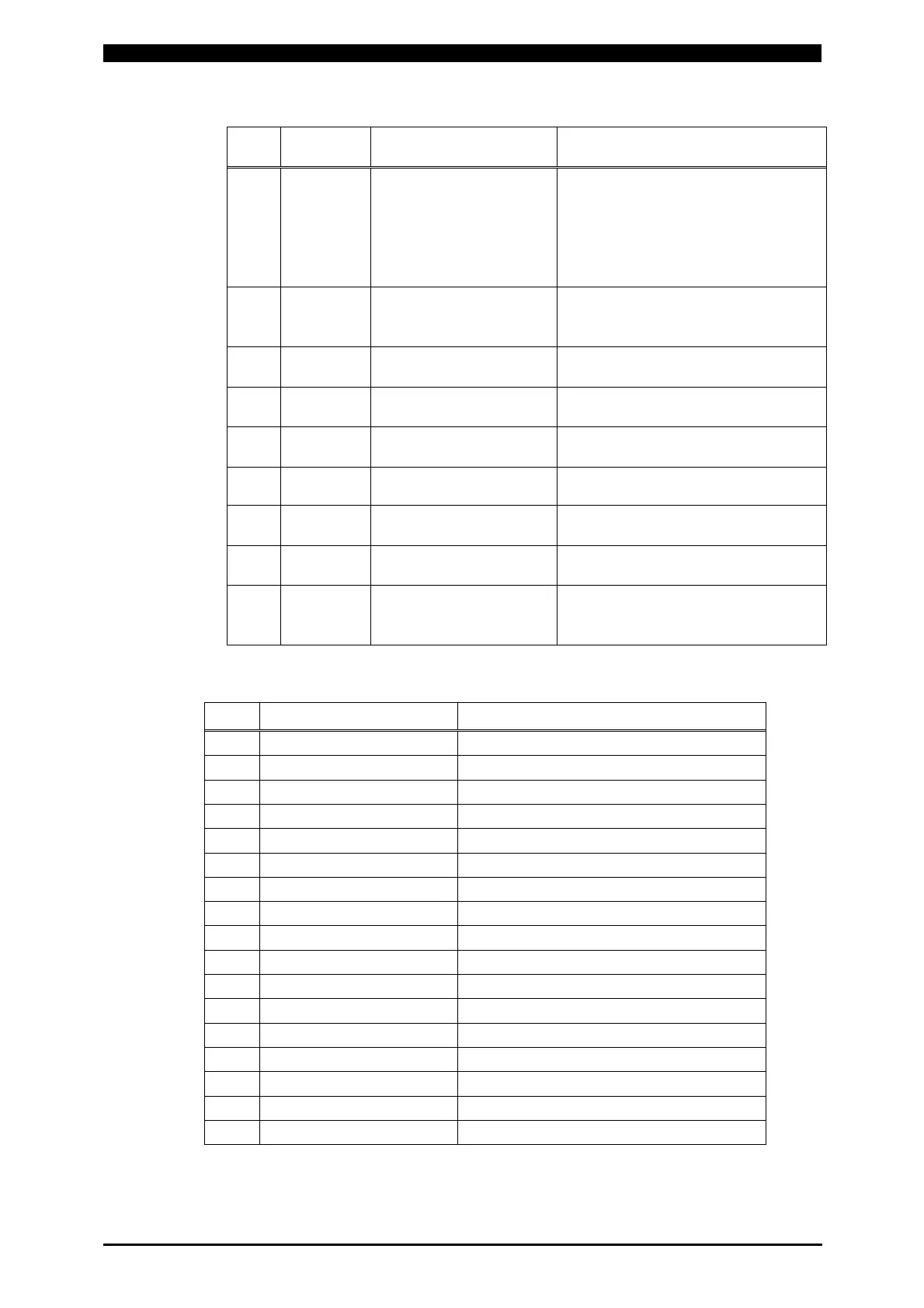
Orde
Character
String
Item Notes
5 nn,
Schedule Select
Method
00: Closed Circuit of Schedule
Select Terminal (No Parity)
01: Closed Circuit of Schedule
Select Terminal (Parity
Valid)
02: Select on Front Panel
6 nn,
End Signal Output
Time
00: 10ms
01: 100ms
02: While Start Signal Output
7 nn, Monitor Mode
00: Slope Time Excluded
01: Slope Time Included
8 nn,
Transformer
Scan Mode
00: OFF 01: ON 02: 1-2
03: 1-3 04: 1-4 05: 1-5
9 nn,
No-current Monitor
Neglect Time
00 to 10 (ms)
10 nn,
Pulse Width Monitor
Neglect Time
00 to 10 (ms)
11 nn, NG Output Mode
00: Open Circuit at NG
01: Closed Circuit at NG
12 nn,
READY Output Mode
Setting
00: ON at Weld ON
01: ON at Power ON
13 nn,
Monitor Value
Calculation Mode
00: High Rate Sampling
01: Low Rate Sampling, Faster
Tact Ti m e
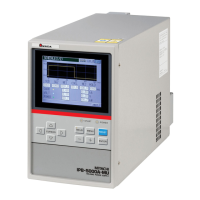
② Order Table of Monitor Data (Most Recent Monitor Value)
Orde
Output Data (n=0 to 9) Content
1
n.nnkA, WE1 Monitor Current (Peak Value)
2
n.nnkA, WE2 Monitor Current (Peak Value)
3
n.nnV, WE1 Monitor Voltage (Peak Value)
4
n.nnV, WE2 Monitor Voltage (Peak Value)
5
nn.nkW, WE1 Monitor Power
6
nn.nkW, WE2 Monitor Power
7
nn.nm*, (Note) WE1 Monitor Resistance
8
nn.nm*, WE2 Monitor Resistance
9
n.nnkA, Precheck Monitor Current
10
n.nnkA, WE1 Monitor Current (RMS Value)
11
n.nnkA, WE2 Monitor Current (RMS Value)
12
n.nnV, WE1 Monitor Voltage (RMS Value)
13
n.nnV WE2 Monitor Voltage (RMS Value)
14
+/-99.999mm Final Displacement
15
nnn.nms W1 Weld Time
16
nnn.nms W2 Weld Time
17
+/-99.999mm Displacement at detecting Workpiece
(Note) The symbol “*” means Ω.