Page 6
Etr This function parameter setting allows external trigger input polarity to be altered. The
settings are
-_- and _-_. The “Reference 150” can be put to sleep and woken via this
voltage monitoring circuit.
APO This function parameter setting allows adjustment of the auto power off time delay. The
settings are 5mins to 60mins and off, incremented in steps of 5. When auto power off is
activated the DATA control must be pressed to bring back on-line manually. This occurs
automatically when audio frequencies above the threshold are present (see Aon).
Memories
4 user presets can be stored. Holding the button down for a few seconds stores the settings for
that preset (store is displayed momentarily). The individual settings can be recalled by a single
press of the corresponding control button. The last selected setting is kept in non volatile mem-
ory. Even if the power is disconnected all settings remain as those last used.
1
2
3
4
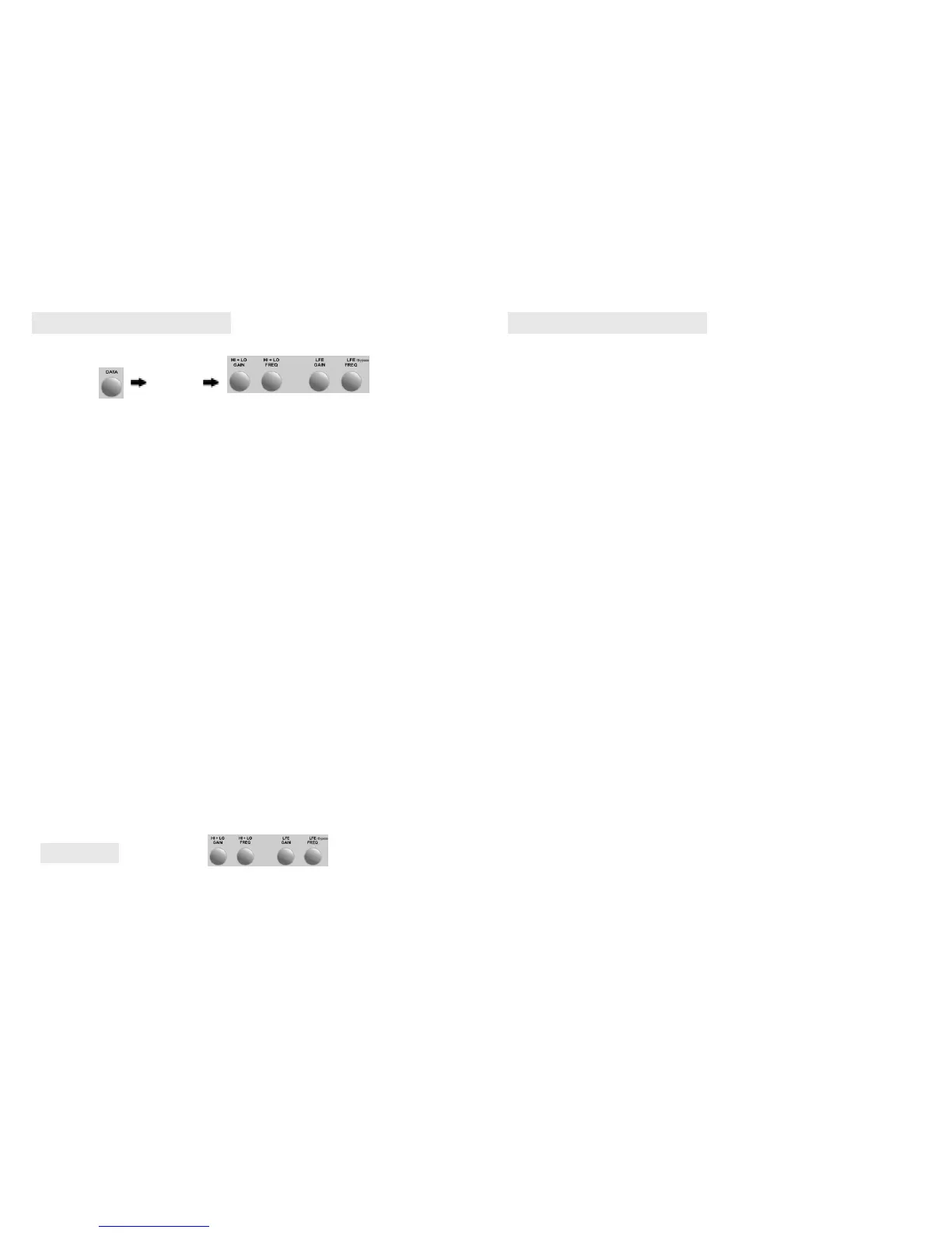
Repeated pressing of the data rotary control scrolls through the menu options as follows:
Hi — Hro — Lo — Lro — Pha — bri — APO — Etr — Aon — dto
Settings can be made at each menu option by turning the rotary control. A further push moves to
the next menu item. At any time settings can be stored in one of 4 user pre-set locations which
are accessed by holding down the corresponding pre-set button (as numbered above).
Reference 150 MkII User’s Manual
1 2
3 4
Press to select
menu item.
Press and hold to store
settings at one of 4
locations
Turn for setting
Pha With the “Reference 150’s” sophisticated microprocessor controlled and monitored
crossover circuit (D.A.M.P.) comes an adjustable phase control. Setting the phase in musically
accurate infinitely variable increments between 0º and 180º. This control is used to enable
accurate and musical integration when placed in a system. By adjusting this control almost
infinite placement combinations can become possible. Most people will not experience phasing.
The effects of which are only apparent to the ear if your main speakers produce the same
frequency note at the same volume level as the subwoofer. For example, if your main speakers
produce a note of 40hz at an equivalent volume level to the subwoofer, also producing 40hz, and
the phase of each is out by 180° then they cancel each other out resulting in a reduction of bass
at this frequency. To remedy this you adjust the phase control on the subwoofer to bring them
both into phase. As a rule of thumb downward, firing subwoofers have a natural 90° out of phase
angle when compared to forward firing main speakers and forward firing subwoofers do not,
when the phase control is set to 0º.
Bri This function parameter setting allows adjustment of the display brightness. The settings
are 1 to 5 with 5 being the brightest. The panel will dim after 20 seconds to its lowest setting until
a command is received.
Aon sensitivity of the auto on circuit can be increased or decreased between 000 and 009.
Dto Display timeout. When selected the display will shut off after 15secs. Use of the remote or
any data rotary movement will bring the display back on.
14/12/2005 (Ref – 150)
Page 11
Using a die-pressed steel chassis of monstrous proportions creates the rigidity
that is so important in sub-bass speaker requirements. Any distortion of the
chassis under extreme load will detract from the goal of pure sound wave formation. As we all
know the creation of sound waves comes directly from the movement of the cone surface
through the air. The longer the movement of the cone, termed as its excursion, the more air it
moves and up goes the sound pressure level. We like to think of our 10” driver as the best of all
worlds. It has agility, rigidity and decelerative damping to enable the cone to move with lightning
speed back and forth through the air. Incorporating an optimised linear motor with progressive
suspension to avoid bottoming and allow maximum linear excursion. The result is extremely low
total harmonic distortion (THD). The voice coil is bonded to the cone to form a one piece
structure. The result is a piston like action adding to the accuracy of the wave formation. Better
heat dissipation and further reduced THD is achieved as a result of the rigid one piece cone
structure together with vented coil exposure. The massive rubber cone surround together with
the semi-rigid lower damping apron serve to bring the cone to an almost instantaneous return to
its resting place between transients. Truly, the muscle of the system and the working end of this
bass producer.
Speaker
D.I.P. (Dynamic Intelligent Protection)
This circuit monitors the output and the input of the amplifier and ensures that no clipping occurs.
Additionally the microprocessor monitors all thermal activity and ensures that the amplifier output
stages remain within safe working area specifications. This is a complex and highly integrated
circuit which continually monitors specific areas and makes the appropriate action should the
need arise.
Reference 150 MkII User’s Manual
D.A.M.P. (Digitally Accurate MicroProcessor)
Digitally Accurate Microprocessor controlled crossover circuit (D.A.M.P.). The
“
Reference 150” has the ultimate in sophisticated crossover circuits. Twin Digitally Accurate
Microprocessor controlled crossover circuits (D.A.M.P.), incorporate a digital display so that the
upper response limit can be set in musically accurate variable increments between 20hz and
120hz. An LFE bypass facility is activated at above 120hz of the LFE controls (Lro) selectable
parameter with a fixed 200hz roll off. All functions are controlled and monitored via microproces-
sor. This development has enabled the complete and highly accurate settings to become part of
user pre-set memories which will enable the user to store desired settings for different music
sources and or music genre’s. The control of all these functions can be made even more flexible
by the use of a remote control device. A remotely located receiver eye is connected to the rear
panel remote jack and any programmable remote can communicate and adjust the required set-
tings. Once setup is complete the cabinet can be turned around to hide the display and connec-
tions, leaving the remote eye to enable the recalling of user stored pre-sets.
Crossover
Standby (auto power off)
This circuit monitors the inputs and wakens the circuits from standby when a signal is present.
Depending on the stored setting for the APO menu item the circuits will fall into standby mode
when lower signal levels are present for the set time. Settings are: Off - 5 - 10 - 15 - and so on
upto 60 mins. Standby and wake-up can also be activated by external trigger from other equip-
ment. Additionally using the remote will activate standby.
14/12/2005 (Ref – 150)
 Loading...