Do you have a question about the MKS Baratron 631F and is the answer not in the manual?
Definitions of WARNING, CAUTION, and NOTE messages used throughout the manual.
Table describing symbols that may be found on the unit.
General safety precautions to be observed during all phases of operation of the instrument.
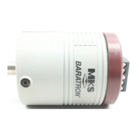
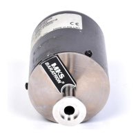
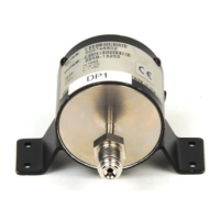
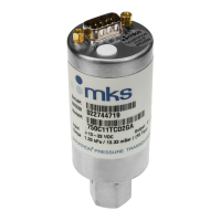
Introduces the MKS Baratron® Type 631F Absolute Pressure Transducer and its features.
Explains the structure and content of the manual for setup, installation, and operation.
Information on standard maintenance, repair services, and contact for MKS Calibration and Service Centers.
Instructions for unpacking the unit and checking for shipping damage.
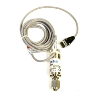
Details MKS interface cables for connecting the 631F unit to a system.
Specifies voltage, current, overpressure limits, mounting, grounding, and vibration isolation.
Details operating ambient temperature, airflow, and storage conditions for the unit.
Guidelines for obtaining maximum accuracy, including piping and component installation.
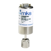
Describes the absolute sensor, its design, and operation based on capacitance change.
General guidelines for line tap, interconnecting piping, and purging.
Lists available fittings for the Type 631F transducer and special notes.
Explains the Type 631F transducer's absolute sensor, its design, and operation.
Describes the self-compensated signal conditioner and its output characteristics.
Details the 15-pin male D-subminiature connector and its pinout.
Explains the 0 to 10 VDC output signal relative to pressure.
Discusses transducer behavior and limits under overpressure conditions.
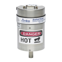
Describes the three labels on the 631F unit: wiring, danger hot, serial number.
Provides initial and periodic procedures for checking and setting the transducer zero.
Step-by-step guide to adjust the ZERO potentiometer for zeroing the unit.
Instructions for using the coarse zero switch when the potentiometer is insufficient.
Explains the function of heater status LEDs and the heater alarm relay.
Details the over-temperature protection mechanism and its indicators.
Introduces the optional trip point relays and their visual indication LEDs.
Details trip point values and how to adjust them using POTs.
Defines how pressure change direction affects relay ON/OFF state and hysteresis.
Recommendations for maintaining accuracy and repeatability, including zeroing and calibration.
Provides solutions for common issues like erratic output and wiring problems.
Lists dimensions, fittings, ranges, input requirements, and materials.
Details accuracy, compliance, temperature coefficients, and time response.
Specifies ambient operating temperature, humidity, and storage temperature ranges.
Explains how the model code identifies transducer options like range and units.
| Brand | MKS |
|---|---|
| Model | Baratron 631F |
| Category | Transducer |
| Language | English |