MBM-Series Owner’s Manual
8
Copyright© 2015 Mod-U-Blast®, All Rights Reserved
How MBM-Series Systems Work Pressure Hold with APV T-Valve & APV II
Warning: This section of the manual is designed to give you a general understanding of how the
Abrasive Blaster functions. ALL sections of this manual must be read and understood before operat-
ing the equipment.
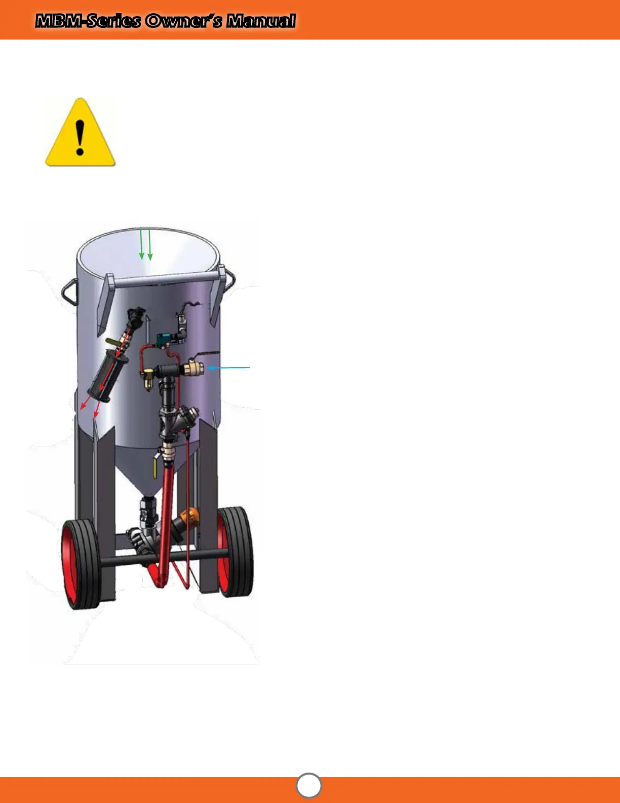
ADDING ABRASIVE
Abrasive is added through the hole in the top of the blaster
where the pop-up and seal are located. It ows down through
the hole, around the pop-up, and down the bottom of the
pressure vessel where it exits through the metering valve.
PRESSURIZATION
Before pressurization can take place in a pressure hold system,
the blow down valve must be closed. Then, when a com-
pressed air source (such as an air-compressor) is connected to
the inlet of the Abrasive blaster and the inlet valve is opened,
compressed air ows and into the pressure vessel causing the
Pop-Up (located internally) to seal against its seat allowing
the pressure vessel to become pressurized. When the control
handle is activated, the Auto Air Valve and Metering Valve
open allowing compressed air and abrasive to ow and mix.
The mixture of compressed air will now exit the Abrasive Blaster
through a blast hose and nozzle connected to the coupling on
the metering valve and blasting begins.
DEPRESSURIZATION (Blow - Down)
When the control handle is released in a pressure hold system,
(MBM Blast Pots with T-Valves) the pressure vessel remains lled
with compressed air. The compressed air remaining in the pres-
sure vessel is released when the inlet valve is manually closed
and the blow-down valve is manually opened.
Loaded Abrasive
Compressed
Air Inlet
Exhausted
Air
 Loading...