EasyManua.ls Logo

Mod 102+ - User Manual

Mod 102+
18 pages
To Next Page IconTo Next Page
Loading...
1 Copyright © 2015 by modkitsdiy.com
Use these instructions to learn:
How to build a tube amp.
This tube guitar amplifier circuit is based on a classic American circuit design combined with a British style
class A output section. At low volume it produces a clean chimey tone that moves into smooth overdrive at
higher volumes.
MOD 102+ GUITAR AMP KIT (K-MOD102+)
+ features include a three position progressive toggle switch for off-standby-power and additional push-pull
functionality for each control:
Pull out the bass control knob for “mid boost.”
Pull out the treble control knob for “bright.”
Pull out the volume control knob for “turbo.”
MOD 102+
TUBE AMP KIT
BASS
®
modkitsdiy.com
Pull-MID BOOST
5
2 8
1
7
0
10
9
4
3
6
VOLUME
Pull-TURBO
5
2 8
1
7
0
10
9
4
3
6
TREBLE
Pull-BRIGHT
5
2 8
1
7
0
10
9
4
3
6
ON
OFF
STBY STBY
Question and Answer IconNeed help?

Do you have a question about the Mod 102+ and is the answer not in the manual?

Mod 102+ Specifications

General IconGeneral
BrandMod
Model102+
CategoryAmplifier
LanguageEnglish

Summary

MOD 102 Guitar Amp Kit Background

Tool List

List of tools required for building the MOD 102+ Guitar Amp Kit.

Parts List

Safety Precautions

The One Hand Rule

Safety precaution for working with live circuits, preventing shock by keeping one hand away from chassis.

Soldering Techniques

De-soldering Tip

Method for removing old solder using a de-soldering tool.

Wiring Best Practices

Wire Connection Conventions

Guidelines for twisting wires and crossing wire paths for optimal performance.

Hardware Fastening Guide

Section 1: Mounting of Top Components

Section 2: Mounting of Front Components

Mounting the Controls

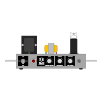
Instructions for mounting the bass, treble, and volume potentiometers.

Section 3: Mounting of Rear Components

Section 4: Mounting Terminal Strips and Components

Step 2: Solder Components to Terminal Strip Locations

Guidance on soldering components to their designated terminal strip locations.

Connect Transformer Wires

Instructions for connecting wires from the power and output transformers.

Section 5: Connect Rear Mounted Components

Insert and Connect the Power Cord

Procedure for installing the power cord and connecting it to the fuse holder and switch.

Section 6: Connect the Tube Filament Wiring

Section 7: Finishing Up

Double Check Your Work

Final review of the assembly to ensure all connections are correct and secure.

Final Operation and Testing

Label Mounting Instructions

Related product manuals