Insert and connect the power cord:
16
1) Install the grommet with ¼” center into the rear chassis hole.
2) Gently insert the power cord through this grommet hole until at least 18" (1.5 FT) are through. Tie a knot
at the end of the cord so that 1" of black outside insulation extends past the knot. This knot will serve as a
strain relief. Pull the knot as tight as possible by hand. Gently pull the cord back through the grommet from
outside of the chassis until the knot is snug against the inside face of the grommet.
5) Connect the power cord’s white wire to power switch lug 4 (see Drawing 8).
3) Connect the power cord’s black wire to the central lug on the fuse holder.
4) Connect the power cord’s green wire to T2(1).
SECTION 6 – Connect the Tube Filament Wiring
Drawing 8 shows the inside chassis view with the filament wiring connected. Use the green wire for these
connections and try to follow the wiring path in the drawing.
Connect the filament wires from lamp holder to V2:
1) Cut two pieces of green wire (about 8.5” each) and connect one end of each to the lamp holder solder lugs.
2) Intertwine these two wires and fasten, but do not solder, one wire to V2(4) and the other to V2(5).
3) Cut two more pieces of green wire (about 5.5” each) and connect one wire’s end to V2(4) and the other
wire’s end to V2(5). Now, solder all connections at V2(4) and V2(5).
4) Twist these two wires together and connect one wire to V1(9) and the other wire to both V1(4) and V1(5).
Double check your work:
1) At this point, most people will feel anxious to start playing through their amp; however, it’s important to
double check your work before applying power. Everyone makes mistakes and it’s easy to forget things. Take
some time now to thoroughly double check your work with Drawing 8. Make sure all solder connections are
sturdy and that the polarized components are connected the right way.
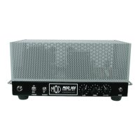
1) Use the four self-tap screws to fasten the chassis cover onto the amp.
2) Remove the four rubber bumpers from their backing and stick them to the cover plate to serve as feet. A
good place to put them would be near each self-tap screw.
Put the tubes in their sockets:
Attach the chassis cover and rubber bumpers:
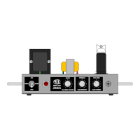
1) Flip the amp over and place the tubes into their respective sockets. The EL84 goes in V2 with the retainer
holding it down.
2) The 12AX7/ECC803 goes in the V1 socket with the tube shield holding it down.
SECTION 7 – Finishing Up
Connect the filament wires from V2 to V1: