13
1) Connect the 6.8K resistor from the bass pot’s c-lug (“cold” lug) to mid-boost
switch lug 2, but do not solder either connection point, yet.
2) Connect the .047 µF cap from the bass pot’s c-lug to T3(1). Now, solder these connections.
4) Connect the .1 µF cap from T3(1) to the bass pot’s w-lug (“wiper” lug), but do not solder at the w-lug, yet.
Connect the T3 and bass pot components:
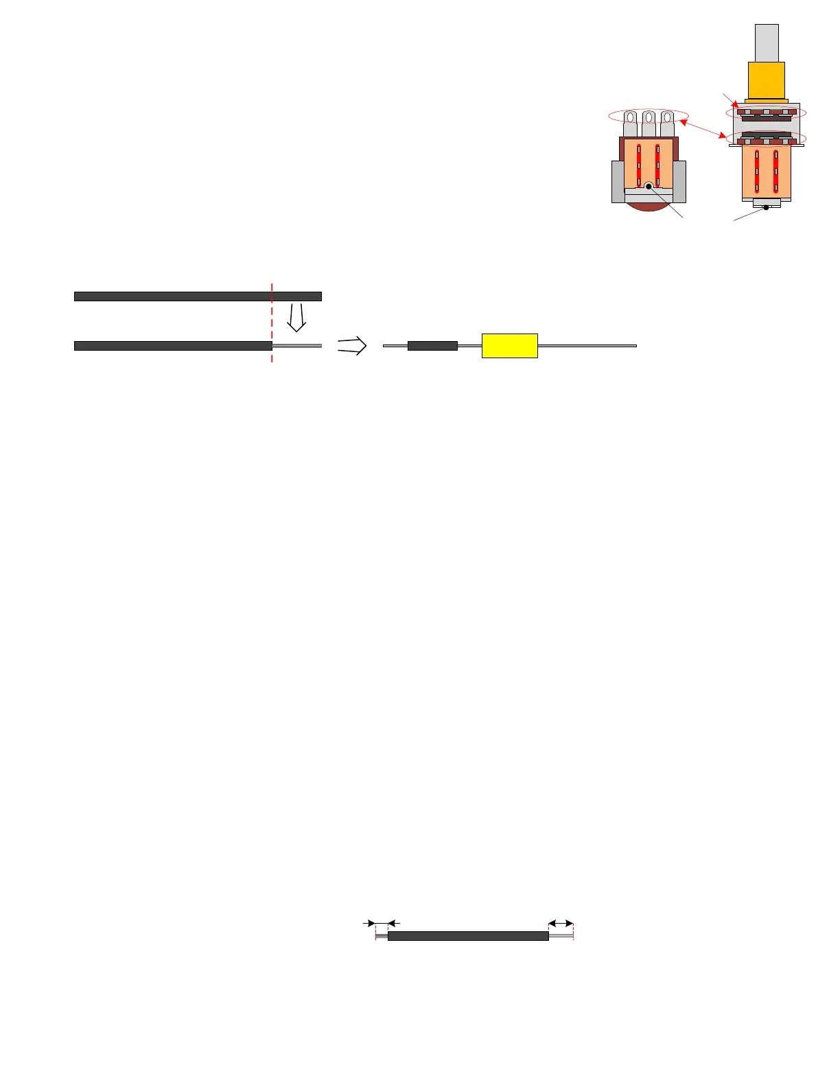
The bass and treble controls are dual 250K pots with a DPDT push-pull switch attached.
The front pot section, closest to the front panel, will not be used. The DPDT lug
numbering is shown in the drawings.
3) Connect one lead of the 10K, ½ watt resistor to mid-boost switch lug 2 and connect the other lead to both
mid-boost switch lug 3 and the body ground terminal. Now, solder these connections.
5) Connect a 2" piece of white wire from the bass pot’s w-lug to the treble pot’s c-lug. Now, solder these
connections.
6) Connect a 100K resistor from T3(1) to T4(5).
Connect the treble pot components:
w hc
1
2
3
4
5
6
w
h
c
Unused front
potentiometer
section
1
2
3
4
5
6
Body ground
terminal
Tip: When making the capacitor connections at this pot, it is important that
the leads do not accidentally touch the pot/switch body or a different lug
than intended. If you feel it is necessary to insulate the capacitor leads, you
might consider doing so by stripping some of the insulation from the black
22 AWG wire and sliding it over the capacitor leads.
.047µF
400V
1) Connect a 2 ¾” piece of white wire from the treble pot’s w-lug to the volume pot’s h-lug (“hot” lug). Do
not solder these connections, yet.
2) Connect a 150 pF capacitor from the treble pot’s w-lug to bright switch lug 4. Solder all connections now.
3) Connect the 250 pF capacitor from the treble pot’s h-lug to T4(5).
4) Connect a 2" piece of black 22 AWG wire from bright switch lug 5 to the volume pot’s wiper lug. Do not
solder the wiper lug connection, yet.
Tip: The black 22 AWG stranded wire is supplied because the white solid-core wire is too thick to fit through
the switch lugs. Normally, it’s a good idea to strip and tin ¼” at the stranded wire ends before making the
connections. In this case, on the end that will connect to the switch lug, just strip 1/8" and do not tin that end.
1/8”
1/4”
Do not tin
this end.
Tin this
end.
Switch End Pot End