Diagram Selection
Diagrams are provided for both single- and three-phase circuits,
and are readily identified in the Selection Table on the following
page. The Selection Table enables easy selection of the correct
wiring diagram after the electrical components of the unit heater
have been determined. The control codes are listed to aid in
locating the correct diagram.
Diagram Interchangeability
The following gas-fired unit heater wiring diagrams are for either
115-volt, 60-Hertz, single-phase power, or for 230-volt, 575-volt,
60 Hertz, three-phase electrical service.
The 115v/60Hz/1φ diagrams may also be utilized for
230v/60Hz/1φ by substituting 230-volt components in the 115-
volt shown.
The 230v/60Hz/3φ diagrams may be modified to 460v/60Hz/3φ
by adding a 460v to 230v step down transformer and wiring the
unit as shown in the wiring “inset” on all 3-phase wiring
diagrams.
The 460v/60Hz/3φ diagrams may be modified to 575v/60Hz/3φ
by adding a 575v to 230v transformer and wiring the unit as
shown in the wiring “inset” on all 3 phase diagrams.
NOTE:
As indicated in every diagram, all wiring must comply
with the national electrical code and all local codes. All
components must agree with their respective power source.
To facilitate interpretation and enable simplification the
abbreviations and symbols have been selected as
recommended by ANSI (American National Standards
Institute) and NEMA (National Electrical Manufacturers
Association) standards.
XFMR or TR Transformer
V Volts
Hz Cycle or Hertz
φ Phase
LC Limit Control
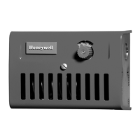
THERM or TH Thermostat
MV Main Valve
PV Pilot Valve
SO Shut Off
RC Relay Contact or Coil
G Ground
H Hot
SW Switch
EPS Electric Pilot Switch
HI High
Lo Low
C Common
“J” Box Junction Box
H1, H2, etc. Transformer Primary Terminals
SUM Summer Contact (Summer/Winter
Switch)
WIN Winter Contact (Summer/Winter
Switch)
S-W Summer/Winter Switch
O.L.C. Overload Contact
C.S. Power Venter Centrifugal Switch
FTc Fan Timer Contact
SPDT Single-Pole Double-Throw Switch
VA Volt-Ampere
W Watts
WIRE COLOR CODING
BK Black
BL Blue
R Red
W White
Y Yellow
X1, X2, etc. Transformer Secondary Terminals
L1, L2, etc. Electric Load Terminals
T1, T2, etc. Starter or Motor Terminals
November, 1997
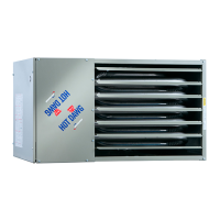
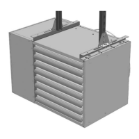
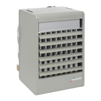
WIRING DIAGRAMS
Models PV/BV gas-fired unit heaters
(manufactured after April, 1994)
6-440.2
Abbreviations and Symbols
CAUTION
Turn off all power and gas to unit before wiring. Failure to
wire this unit according to the specified wiring diagram may
result in injury to the installer or user. For deviations, contact
factory.