Do you have a question about the Modine Manufacturing PTP and is the answer not in the manual?
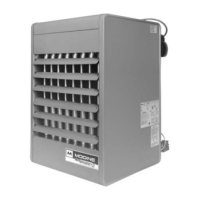
Describes power-vented unit heaters for residential, commercial, and industrial applications.
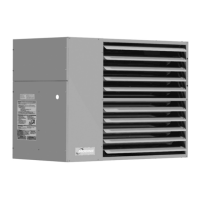
Details separated combustion unit heaters for residential, commercial, and industrial use.
Features high-efficiency separated combustion units for commercial and industrial applications.
Highlights features and benefits of the Model HD unit heater, including efficiency and installation.
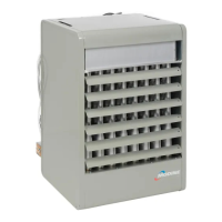
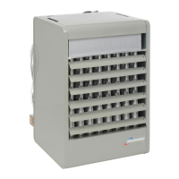
Details features and benefits of the Model PDP unit heater, emphasizing ease of use and economy.
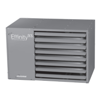
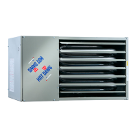
Outlines features and benefits of the Model PTP unit heater, noting its stainless steel heat exchanger.
Explains benefits of separated combustion for improved performance and durability.
Details benefits of separated combustion for improved performance and durability.
Describes the high-efficiency Model PTC with Conservicore® technology and 97% thermal efficiency.
Highlights benefits of blower unit heaters for heating and ventilating applications.
Provides performance data for HDB and BDP blower models.
Presents performance data for the Model BTC blower unit heater.
Details performance data for HDC and BTS separated combustion blower models.
Lists benefits of infrared heating, including no air mover, quick recovery, and energy savings.
Provides examples of applications for high-intensity and low-intensity infrared heating.
Specifies allowable mounting angle ranges for IHR heaters.
Provides clearance requirements to combustible materials for IHR heaters.
Details clearance requirements to combustible materials for OHP heaters.
Specifies clearances to combustible materials for IPT units.
Covers general construction, mechanical configuration, and venting for IHR heaters.
Details burner operation temperature and radiant output.
Describes reflector construction and adjustability.
Outlines control systems, including pilot ignition and direct spark ignition.
Lists available field installed accessories for IHR heaters.
Covers general construction, casing, heat exchanger, controls, and motor.
Provides performance data for HD and PDP propeller units.
Details operating electrical data for HD and PDP propeller units.
Provides general performance data for PTP and BTP models.
Details operating electrical data for PTP propeller units.
Shows motor amp draw for BTP blower models across various voltages.
Details control circuit amp draw for BTP blower models.
Lists accessory transformer sizes (kVA) for BTP blower models.
Describes power codes for BTP blower models, relating them to HP, Drive, and Turns.
Provides filter static pressure drop values for BTP units.
Presents blower performance data for BTP 150-250 models with various static pressures.
Lists alternate drives for 208-230/460V 3 Ph, 1 HP motors.
Lists alternate drives for 208-230/460V 3 Ph, 1-1/2 HP motors.
Lists alternate drives for 575V motors.
Describes power codes for HDB models.
Lists power code descriptions for BDP blower models.
Details electrical and control code selections for all models.
Provides gas control information for various models.
Lists available field installed accessories for various Modine models.
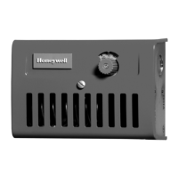
Describes available thermostats for field installation.
Provides performance data for downtown hoods on HD/PDP/PTP models.
Details deflector hood performance for BTP/BTS blower models.
Presents performance data for BDP blower velocity generating nozzles.
Guides users through the steps for selecting a unit heater.
Provides an example scenario for selecting a propeller unit heater.
Details the solution for the propeller unit selection example.
Presents an example scenario for selecting a blower unit heater.
Details the solution for the blower unit selection example.
Provides dimensional data for Model HD heaters.
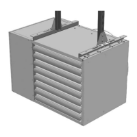
Provides dimensional data for Model HDB heaters.
Specifies clearances to combustible materials for HD/HDB models.
Provides dimensional data for PDP models.
Illustrates clearances to combustible materials and service for PDP models.
Provides dimensional data for BDP models.
Specifies clearances to combustible materials for BDP models.
Lists applicable ETL and ETL Verified design certifications.
Details mechanical configuration including efficiency and heat transfer.
Specifies power exhausted venting and differential pressure switch requirements.
Describes casing construction materials and finish.
Details heat exchanger and burner construction and thermal efficiency.
Covers control systems, gas pressure, and safety features.
Specifies electrical component requirements including UL/ETL/CSA listing.
Details motor horsepower, wiring, and propeller/blower model requirements.
Describes unit mounting requirements using tapped holes or brackets.
Lists field installed accessory control devices.
Specifies thermostat types and connection requirements.
Illustrates how to interpret the model number designations.
Details warranty periods for various components like heat exchangers, burners, and motors.
Instructions for inspecting the unit upon arrival for damage and conformance.
Lists critical precautions for safe and efficient operation.
Defines hazard intensity levels: DANGER, WARNING, CAUTION, IMPORTANT.
Provides safety instructions, including what to do if you smell gas.
General safety and installation precautions to follow.
Defines hazard intensity levels: DANGER, WARNING, CAUTION, IMPORTANT.
Provides preliminary steps and compliance information before installation.
Lists conversion factors for SI (Metric) units.
Provides guidance on selecting appropriate unit locations.
Specifies clearances to combustible materials for various unit sizes.
Details requirements for combustion air supply in confined and unconfined spaces.
Discusses sound and vibration attenuation for mechanical equipment.
Provides general instructions applicable to all venting installations.
Details installation procedures for vertical Category I vent systems.
Provides installation instructions for horizontal Category III vent systems.
Lists minimum clearances for vent termination based on structure and location.
Outlines ANSI requirements for unit heater venting based on category.
Illustrates vertical Category I vent system termination.
Specifies minimum vent height from roof based on pitch and discharge opening.
Diagram for vertical single wall vent termination from adjacent structures.
Diagram for vertical single wall vent termination from adjacent structures.
Illustrates exhaust vent construction through combustible walls.
Shows horizontal Category III venting with upward pitch.
Illustrates horizontal Category III venting with downward pitch and drip leg.
Specifies minimum length between external wall and vent cap.
Lists minimum clearances for vent termination.
Provides maximum appliance input capacities for Type B vent connectors.
Specifies max appliance input capacities for Type B vent connectors into masonry chimneys.
Illustrates recommended sediment trap and manual shut-off valve installation.
Shows sea level manifold pressure and gas consumption data.
Provides gas pipe capacities for natural gas based on length and diameter.
Lists natural gas heating values at various altitudes for USA and Canada.
Lists propane gas heating values at various altitudes for USA and Canada.
Provides equation to determine manifold pressure for derated gas.
Specifies high altitude kits required for PDP/BDP models based on altitude.
Outlines electrical requirements including voltage, grounding, and wire size.
Shows recommended ductwork installations for blower units.
Details requirements specific to BDP blower models.
Explains how to determine and adjust blower speed using motor sheaves.
Describes how to adjust blower motor speed using sheave settings.
Outlines steps to perform before initial unit operation.
Provides lighting instructions and sequence of operation for direct spark ignition.
Details lighting instructions and sequence of operation for millivolt systems.
Explains the sequence of operation for units with intermittent pilot systems.
Guides on adjusting manifold pressure for proper burner operation.
Details how to adjust natural gas and propane flames for proper operation.
Provides instructions on adjusting the pilot flame length.
Describes single-stage and two-stage gas valves.
Details the factory-installed ignition controller.
Explains the function of the time delay relay.
Describes the low voltage terminal board location and labeling.
Details the control step down transformer's function and usage.
Explains the automatic reset high limit switch function.
Describes the automatic reset vent pressure switch function.
Details the standard power exhauster supplied with units.
Describes the blower motor, its adjustability, and options.
Provides performance data for PDP propeller models.
Presents performance data for BDP blower models.
Lists performance data for BDP blower models with or without enclosure.
Provides performance data for hoods based on mounting height, throw, and spread.
Outlines annual maintenance checks for the unit and venting system.
Provides general cleaning and inspection guidelines for the unit heater.
Recommends checking electrical wiring for loose connections annually.
Advises annual checks on gas valves and piping for cleanliness and tightness.
Guides on checking the propeller motor for lubrication and fan condition.
Details checks for blower bearings, drive sheaves, and belts.
Provides step-by-step instructions for removing the manifold assembly.
Details the procedure for removing the burner and pilot assembly.
Lists common trouble symptoms, possible causes, and possible remedies.
Illustrates the format and meaning of serial number designations.
Explains the structure and meaning of model number designations.
| Brand | Modine Manufacturing |
|---|---|
| Model | PTP |
| Category | Heater |
| Language | English |