EasyManua.ls Logo

Moeller NZM 14 Series User Manual

Moeller NZM 14 Series
9 pages
To Next Page IconTo Next Page
Page #1 background imageLoading...
Page #1 background image
12/98 AWA 123-1455
PPTTPP
Montageanweisung
Installation Instructions
Notice d’installation
Istruzioni per il montaggio
Instrucciones de montaje
Инcтpyкция пo мoнтaжy
NZM 14-...(S)(H)
NZM 144-...(S)(H)(
/
0)
1/10
SW 19
4 u
12 u
Lebensgefahr durch elektrischen Strom!
Nur Elektrofachkräfte und elektrotechnisch
unterwiesene Personen dürfen die im folgen-
den beschriebenen Arbeiten ausführen.
Electric current! Danger to life!
Only skilled or instructed persons may carry out the
following operations.
Tension électrique dangereuse !
Seuls les personnes qualifiées et averties doivent exécuter
les travaux ci-après.
Pericolo di morte causa corrente elettrica!
Solo persone istruite e avvertite possono eseguire le
operazioni di seguito riportate.
¡Corriente eléctrica! ¡Peligro de muerte!
El trabajo a continuación descrito debe ser realizado
por personas cualificadas y advertidas.
Элeктpичecкий тoк! Oпacнo для жизни!
Toлькo cпeциaлиcты или пpoинcтpyктиpoвaнныe
лицa мoгyт выпoлнять cлeдyющиe oпepaции.
H 1
H 2
Question and Answer IconNeed help?

Do you have a question about the Moeller NZM 14 Series and is the answer not in the manual?

Moeller NZM 14 Series Specifications

General IconGeneral
BrandMoeller
ModelNZM 14 Series
CategoryIndustrial Electrical
LanguageEnglish

Summary

Product Introduction and Safety

General Safety Warnings

Critical safety instructions regarding electrical hazards and qualified personnel.

Product Identification

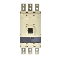
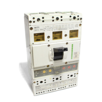
Identifies the specific product models covered by the manual.

Mounting Instructions

Device Mounting Orientation

Illustrates correct mounting positions and angles for the device.

Mounting Plate and Angle Usage

Guidance on using the MW-NZM 14 fixing angle with a mounting plate.

Electrical Connection Details

Terminal Connections and Torque Specs

Specifies terminal connection procedures and required torque settings.

PTP Terminal Wiring for Current Ratings

Wiring diagrams for PTP terminals according to different current ratings.

Device Setting Parameters

Basic Current and Overcurrent Settings

Configures basic current (Io) and time-delayed/instantaneous overcurrent protection (Ir, tr).

Earth Fault and Short-Circuit Protection

Sets earth fault (Irmv, tv) and short-circuit protection (I2t, Irm) parameters.

Advanced Settings and Modules

Short-Circuit and Maximum Current Settings

Adjusting short-circuit (I2t) and maximum current (Irm) protection parameters.

Additional Current Transformer Connection

Connecting an additional current transformer for 3-pole switches in 4-pole networks.

LUE Module Operation

LUE Module Wiring and Alarm Indicators

Wiring the LUE module and interpreting its LED alarm indications.

M Module Operation

M Module Wiring and LED Status

Wiring the M module and interpreting the status of its LEDs.

Operation and Testing Procedures

Sealing and Test Button Operation

Instructions for sealing the device and using the 'Push to trip' test button.

Technical Dimensions

Device Size and Mounting Hole Layout

Provides dimensions and layout for mounting holes.

Related product manuals