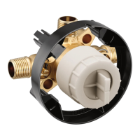
Installation of the cartridge:
1. Verify that the cartridge is properly set by aligning the drilled hole in
the cartridge stem to the indent on the cartridge body.
2. Assemble the temperature limit stop to the cartridge ensuring that
the key on the temperature limit stop is aligned to the slot in the cartrige.
3. By pushing on the front of the temperature limit stop, insert cartridge into
the valve body until the temperature limit stop key is fully seated into the valve.
page 4page 11
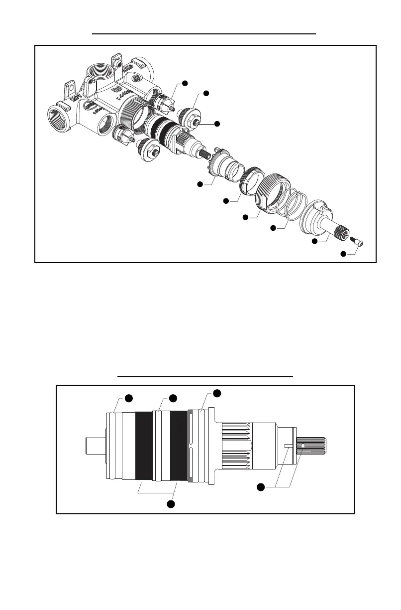
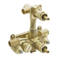
CARTRIDGE SERVICING EXPLODED VALVE DIAGRAM
CARTRIDGE DIAGRAM
1. Check Valve 6. Handle Adapter Nut
2. Stop Body 7. Spring
3. Stop Stem 8. Stem
4. Temperature Limit Stop 9. Screw
5. Cartridge Nut
For service kit numbers refer to moen.com
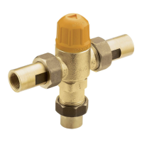
1. Bottom O-Ring 5. Pre-Set Temperature Alignment
2. Middle O-Ring Markings (105˚)
3. Top O-Ring
4. Screens