7
Monessen • BLOTMC Installation Manual • 93D0005 • Rev H • 01/2020
NOTE: Pertaining to LCUF32CR-B, LCUF36CR-B,
LCUF42CR-B
Thermal Sensor Installation:
1. Remove burner and log set if previously installed.
2. Remove rebrick.
3. Remove rear and side access panels. See Figure
19.
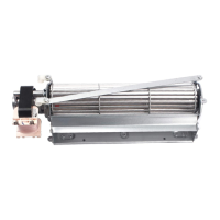
Correct placement
for Thermal Sensor
Figure 20
4. Install wires from thermal sensor into hole on right
side. See Figure 20.
5. Thermal sensor should be installed in large hole
and slid down into place. The tabs of the thermal
sensor should rest against the venting support. At-
tach the thermal sensor with 1 screw nearest the
opening.
6. The 2 wires should be visible from the side access
panel.
7. Pull the wires toward the back of the unit toward the
rear access panel.
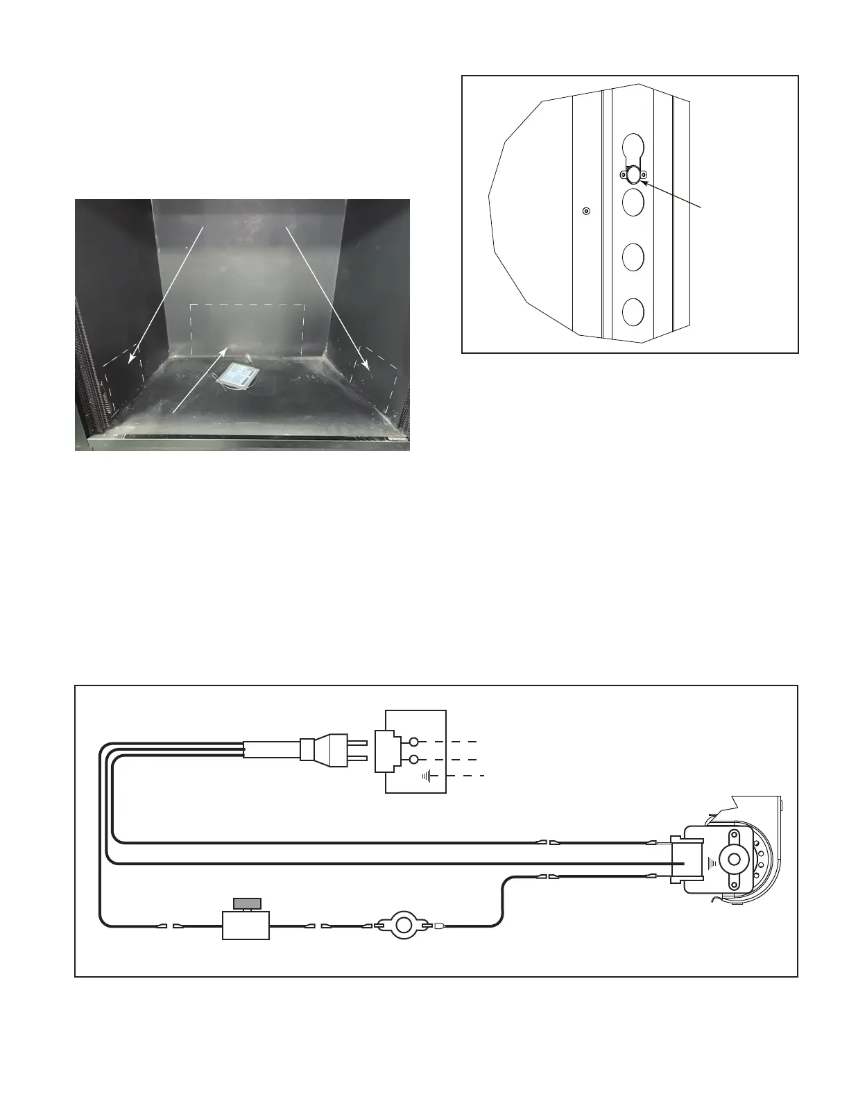
Figure 21
BLACKBLACKWHITE
GREEN
BLACK BLACK
WHITE
Receptacle
Junction
Box
120VAC
Speed Control
WHITE
BLACK
Extension Wire
Side Access Panel
Rear Access Panel
Figure 19
8. Add additional length of wire from blower to speed
control and power cable. See wiring diagram. Fig-
ure 21.
9. Attach wires as per wiring diagram. Figure 13.
 Loading...