Do you have a question about the Monessen Hearth BLOTMC and is the answer not in the manual?
Provides initial steps, model verification, and damage inspection before installation.
Details the three-prong plug and proper grounding for shock hazard protection.
Lists all components included in the blower installation kit.
Specifies the tools needed for the installation process.
Guides on wiring the receptacle, using the junction box, and strain relief connector.
Emphasizes qualified electricians and turning off main power before connecting.
States the BLOTMC blower is for Hearth & Home Technologies vent-free fireplaces only.
Stresses compliance with local regulations and the National Electric Code.
Instructions for units with a pre-installed blower mounting bracket using Velcro strips.
Steps for installing the blower using Velcro directly to the firebox wall and floor.
Attaching the blower switch bracket to the speed control with screws.
Placing the switch assembly in the lower left corner and securing it with screws.
Instructions for removing the knob, switch bracket, and securing the assembly for specific BUF models.
Steps for inserting wires, seating the sensor, and securing it with screws.
Instructions for drilling holes for sensor attachment on specific older BUF models.
Instructions for installing the thermal sensor on all other Monessen burner types.
Guidance on connecting wires as per the wiring diagram and plugging in the power cord.
Warning to arrange wires to prevent contact with blower fan blades.
Steps for testing blower function, adjusting speed settings, and final operation checks.
Instructions for installing the thermal sensor in the VFF series, including wire routing.
Steps for bending the mounting tab and attaching the speed control for IPI systems.
Instructions for attaching the variable speed control to the control panel for millivolt systems.
Connecting wiring, using clips, and plugging into the junction box.
Steps to remove burners, firebrick, and access panels for sensor installation.
Installing the sensor in a large hole and securing it with a screw near the opening.
Adding wire length, routing wires, and attaching them as per the wiring diagram.
Instructions for installing the blower through the rear access panel and routing wires.
Securing the variable speed control to the side access panel and routing wiring.
Confirming wire routing, plugging into junction box, and reinstalling panels and components.
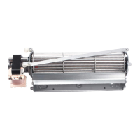
The Monessen BLOTMC is a blower designed for use with vent-free fireplaces manufactured by Hearth & Home Technologies. It is intended to circulate warm air from the fireplace into the room, enhancing heating efficiency.
The BLOTMC blower draws in cooler room air, passes it over the hot surfaces of the fireplace, and then discharges the warmed air back into the living space. This process helps to distribute heat more effectively than radiant heat alone. The blower includes a variable speed control and a thermal sensor, allowing for automatic operation based on fireplace temperature and adjustable airflow. When the fireplace heats up to a certain temperature, the thermal sensor activates the blower. The speed control allows the user to adjust the fan's output, from a gentle circulation to a more powerful airflow, to suit comfort preferences. The blower is designed to be installed within the fireplace's lower access compartment, either with a pre-installed mounting bracket or secured directly to the firebox wall and floor using Velcro.
| Brand | Monessen Hearth |
|---|---|
| Model | BLOTMC |
| Category | Blower |
| Language | English |