- 8 -
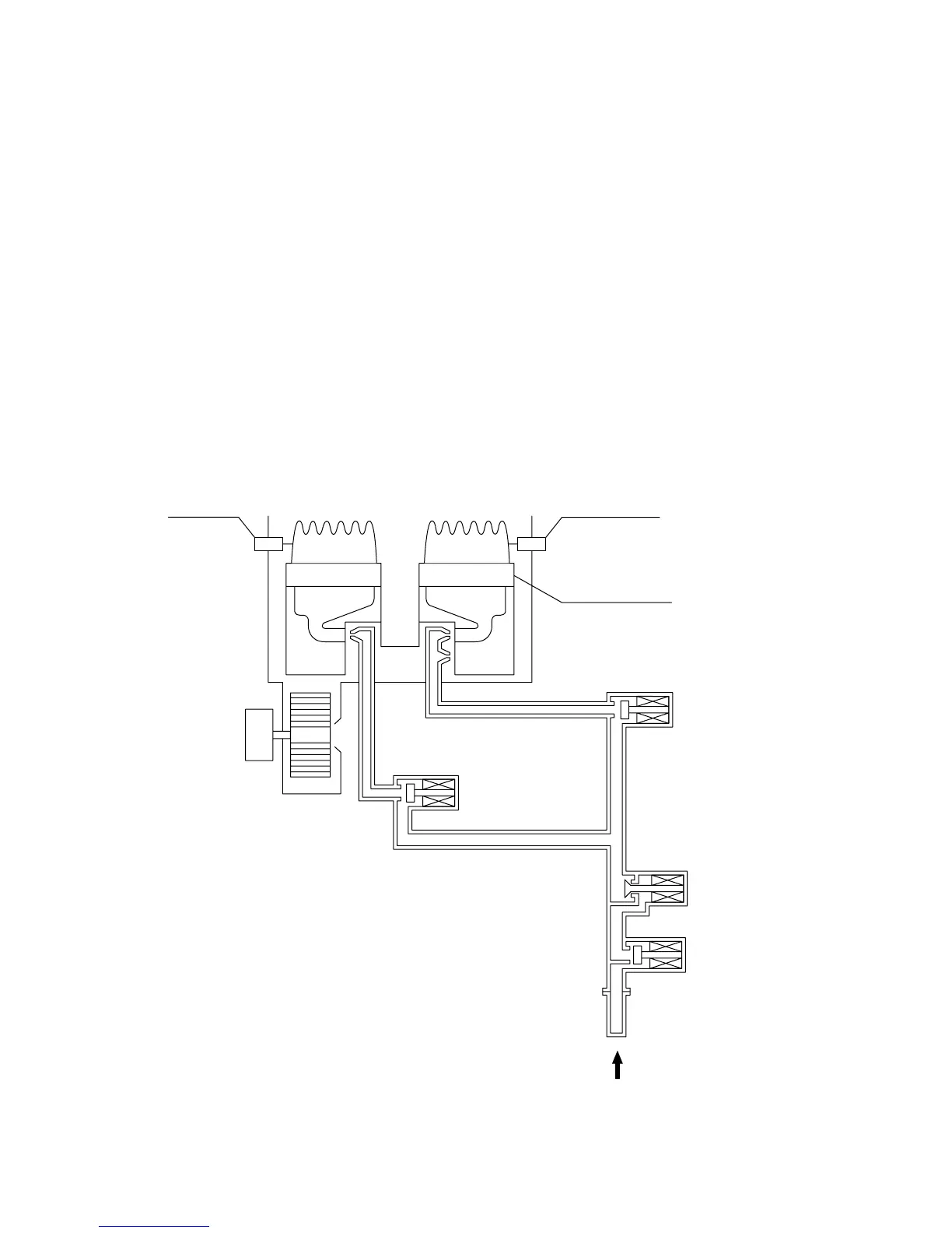
4. Combustion control of rich and lean burners
1) Ignition start
After the Main Gas Solenoid Valve, Gas Solenoid Valve 1, Gas Solenoid Valve 2 open
respectively as required, the Gas Modulating Solenoid Valve, being held at the slow igni-
tion position (with gas supply at a constant rate), operates to ignite rich burners and lean
burners.
2) During combustion
When a heating capacity higher than a certain level (approximately 95,000 BTU) is re-
quired, both Gas Solenoid Valve 1 and Gas Solenoid Valve 2 are opened to burn with rich
and lean burners while the gas supply is controlled by the Gas Solenoid Valve. When the
required heating capacity becomes lower than a certain level (approximately 110,000
BTU), the Gas Solenoid Valve 2 is closed while Gas Solenoid Valve 1 remains open to
combust with 12 rich burners, with the gas supply controlled by the Gas Modulating Sole-
noid Valve.
Gas
Gas Solenoid Valve 2
Gas Solenoid Valve 1
Combustion fan
Electrode
Flame rod
Main burner
Gas Modulating
Solenoid Valve
Main Gas
Solenoid Valve