2.126
2.95
[74.9]
[54.00]
1.812
[46.00]
4.20
[106.7]
2.60
[66.0]
1.57
[40.0]
1.39
[35.3]
3.72
[94.5]
3.84
[97.5]
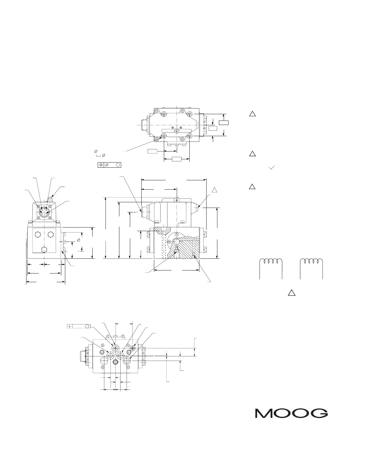
REPLACEABLE FILTER
ELECTRICAL CONNECTOR
PIN B
PIN A
PIN C
PIN D
NULL ADJUST
COVER SCREW
INSTALL SEAL WASHER
AND SCREW FOR
INTERNAL PILOT SUPPLY
SEAL WASHER AND SCREW SHOWN
INSTALLED FOR EXTERNAL PILOT SUPPLY
4.67 MAX
[118.6]
2.76
[70.0]
3.23 MAX
[82.0]
1.063
[27.00]
5.43 MAX
[137.9]
4 X .256 [6.5] THRU
.433 [11.0]
TO DEPTH SHOWN (2.29 REF)
.011
M
2.29
[58.2]
1.38
[35.0]
1.72
[43.7]
.906
[23.00]
5.07 MAX
[128.8]
OPTIONAL MANUAL
OVERRIDE HANDLE 5
O Ø .001 M
4 HOLES
.063
[1.60]
.374
[9.50]
.658
[16.70]
1.417
[36.00]
B
P
T
A
X
.937
[23.80]
.937
[23.80]
.406
[10.30]
.406
[10.30]
Moog Inc.,East Aurora,NY 14052-0018
Telephone:716/655-3000
Fax:716/655-1803
Toll Free:1-800-272-MOOG
NOTES
TYPICAL WIRING SCHEMATIC
The products described herein are subject to change at any time without notice, including, but not limited to, product features, specifications, and designs.
1 Fluid:
Industrial type petroleum base
hydraulic fluid,maintained to ISO DIS
4406 Code 14/11 recommended.
2 Operating Temperature Range:
0°F [-18°C] TO +200°F [+93°C].
3 Valve Phasing:
Flow out port B results when:
Series coils:B & C connected, A+,D-;
Parallel coils:A & C connected,B & D
connected,A+,D-.
4 Surface:
Surface to which valve is mounted
requires
64
( ) finish,flat within .002
[0.05] TIR.
5 Null Adjust:
Flow out Port A results with clockwise
rotation of null adjust set screw (
1
/
8
hex
key).
3
ABCD
∆∆