EasyManua.ls Logo

Moog D661 series

Moog D661 series
16 pages
To Next Page IconTo Next Page
Loading...
CAUTION
DISASSEMBLY, MAINTENANCE, OR REPAIR OTHER THAN IN ACCORDANCE WITH THE
INSTRUCTIONS HEREIN OR OTHER SPECIFIC WRITTEN DIRECTIONS FROM MOOG WILL
INVALIDATE MOOG’S OBLIGATIONS UNDER ITS WARRANTY.
D661 Series
ISO 4401 Size 05
Installation and Operation Instruction
Servo and Proportional Control Valves with Integrated Electronics
1. INTRODUCTION
This manual provides instructions and procedures necessary
to install, operate and troubleshoot the Moog D661 Series Servo and Propor-
tional Control Valves.
2. OPERATION
General
The Servovalves D661-G, S and H Series and the Proportional Flow
Control Valves D661-P Series are throttle valves for 2-, 3- and 4-way
applications. With proportional flow control valves, 5-way applications are also
possible. These valves are suitable for electrohydraulic position, velocitiy,
pressure or force control systems with high dynamic response requirements.
D661-G, S and H
The spool of the main stage is driven by a nozzle flapper or ServoJet
®
pilot stage, optional with or without additional mechanical feedback (nozzle
flapper only).
With versions D661-S and H in case of an electrical supply failure
the spool is moved into a preferred position by action of an additional
mechanical feedback.
ELECTROHYDRAULIC VALVE CUT-AWAY
Figure 1 Moog Series D661-G Series, without additional mechanical feedback
XT A P B T
2
Y
Connector
Spool
Bushing
Screw Plug for Null Adjust
Series Models
Series G Servovalve with nozzle-flapper or ServoJet
®
pilot
stage, spool in bushing, without additional mechanical
feedback
Series S Servovalve configured like version G, but with additional
mechanical feedback
Series H Servovalve configured like version S, but with improved
performance (high response)
Series P...A/B Proportional valve with ServoJet
®
pilot stage, spool in body,
without additional mechanical feedback
Series P...F/G Proportional valve configured like version P...A/B, but
with nozzle flapper pilot stage and additional mechanical
feedback

Other manuals for Moog D661 series

Question and Answer IconNeed help?

Do you have a question about the Moog D661 series and is the answer not in the manual?

Moog D661 series Specifications

General IconGeneral
BrandMoog
ModelD661 series
CategoryControl Unit
LanguageEnglish

Summary

1. INTRODUCTION

Series Models Overview

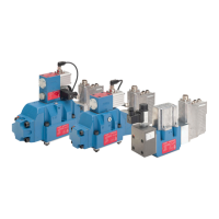
Lists different D661 series valve models and their configurations.

2. OPERATION

General D661 Valve Operation

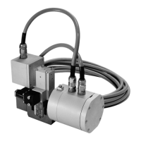
Describes general functionality and applications of D661 series valves.

D661-G, S, H Servovalve Operation

Explains the operation of D661-G, S, and H servovalves with spool drive.

Two-Stage Valve Operating Principle

Details the working principle of two-stage servo and proportional valves.

Failsafe Versions for Proportional Valves

Explains failsafe options for proportional control valves to ensure defined spool position.

Technical Data

3. SAFETY INSTRUCTIONS

General Safety Warnings and Symbols

Explains symbols and general safety warnings to prevent damage or injury.

Correct Application and Organizational Measures

Defines correct usage and organizational requirements for valve operation and maintenance.

Personnel Qualification and Operational Safety

Specifies requirements for personnel training and safety during operational phases.

4. INSTALLATION

General Installation Guidelines

Provides general information and checks before mounting the valve.

Pilot Connection Conversion

Details how to convert between internal and external pilot connections for specific valve types.

5. SETTING UP

Setting Up and Hydraulic System Preparation

Covers procedures for setting up the machine/plant and preparing the hydraulic system.

6. MAINTENANCE

Routine Maintenance and Filter Replacement

Details standard maintenance, filter disk inspection, and replacement steps.

Electronics Information

Valve Connectors and Supply Voltages

Lists available valve connector types and compatible supply voltages.

15 VDC Electronics: Input & Output Signals

Explains command input signals and monitoring output for 15VDC electronics.

15 VDC 11+1 Pole Bayonet Electronics

Details command input and monitoring output for 11+1 pole bayonet connector electronics.

15 VDC 6 Pole Electronics (No Ground)

Covers command input and monitoring output for 6 pole connector electronics without protective grounding.

15 VDC 12 Pole Bayonet Electronics

Details command input and monitoring output for 12 pole bayonet connector electronics.

24 V 6+PE Pole Electronics

Explains command input and monitoring output for 24V 6+PE pole connector electronics.

24 V 11+PE Pole Electronics

Details command input and monitoring output for 24V 11+PE pole connector electronics.

7. Electrical Null Adjustment Procedure

8. Required Tools and Equipment

Troubleshooting Guide

Moog Authorized Repair Facilities

Manufacturer Declaration

D661 Series Ordering Guide

Valve Specification and Identification

Explains how to specify valve series, status, model, and factory identification.

Valve Versions and Rated Flow

Details different valve versions and their corresponding rated flow capacities.

Electric Supply and Signal Options

Lists available electric supply voltages and signal configurations for spool stroke.

Pilot Connections and Pressure Ratings

Describes pilot connection types and maximum operating pressure ratings for valve configurations.

Related product manuals