Valve electronics with supply voltage 24 Volt and 11+PE - pole connector
a. Command input
Command signal 0 to
±10 V
The spool stroke of the valve is proportional to (U
D
– U
E
). 100% valve opening
P ➔ A and B ➔ T is achieved at (U
D
–U
E
) = +10 V. At 0 V command the spool is
in the center position.
The input stage is a differential amplifier. If only one command signal is
available, pin D or E is connected to signal ground (pin B) according to
the required operating direction (to be done at the mating connector).
Command signal 0 to
±10 mA
The spool stroke of the valve is proportional to (I
D
– I
E
). 100% valve opening P➔A
and B ➔ T is achieved at (I
D
– I
E
) = +10 mA. At 0 mA command the spool is in
the center position.
Either pin D or E is used according to the required operating direction.
The unused pin is left open (not connected at the mating connector). The
input pins D and E are inverting.
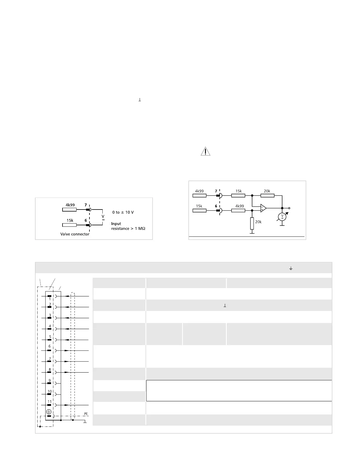
b. Monitoring output
Actual value 0 to
±10 V
Valves with voltage and current command input
The actual value, i. e. the spool position, can be measured between pins 6 and
7. This signal can be used for monitoring and fault detection purposes. The
signal can only be measured using a weighted differential amplifier (see dia-
gram below) or a voltmeter with an input impedance greater than 1M
Ω. The
spool stroke range corresponds to ±10 V. The centered position is at 0 V.
+10 V corresponds to 100% valve opening P ➔ A and B ➔ T.
If the actual value will be used with a machine control system, the differential
input circuit must be used. Another option is to use the aforementioned
circuit for the 6+PE pole connector. Pin 6 according to DIN 43 651
corresponds to pin F according to DIN 43 563 (see diagram page 12).
Circuit diagram for measurement of actual value U
6-7
(position of
main spool) for valves with 11+PE pole connector
Output I
max
: 20 mA
U
6-7
: 0 to ±10 V
R
a
: approx. 20 KΩ
Output I
max
: 20 mA
Input command referenced to ⊥ I
4-5
: 0 to ±10 mA
(load resistance 200Ω)
Input command (invert.) ref. to ⊥ I
5-4
: 0 to ±10 mA
U
8-2
> +8.5 VDC: ok
U
8-2
< +6.5 VDC: not ok
U
11-2
> +8.5 VDC: <30 %
U
11-2
< +6.5 VDC: >30 %
Protective grounding
Enabled
1
)U
3-2
> +8.5 VDC
Not enabled U
3-2
< +6.5 VDC
Supply 24 VDC (min. 19 VDC, max. 32 VDC) I
max
: 300 mA
Supply / signal ground (0V)
Function Voltage command Current command
Output actual value
(differential)
Input rated command
(differential)
not used
not used
Position error
Valves with 11+PE pole connector to DIN 43 651and mating connector (metal shell) with leading protective ground connection ( )
U
4-2
and U
5-2
:
max.: –15 V
max.: +24 V
U
4-5
: 0 to ±10 V
R
e
: 10 kΩ
Enable and Supply
acknowledged
I
e
= 1.2 mA at 24 VDC
Valve Connector
Mating
Connector
Cabinet side
Note: With valve models D661-27XX and D661-29XX supply voltage is at pin 9 and signal
ground at pin 10.
Pins 1 and 2 are not used.
1
) With enable signal < +6.5 V the spool moves into the position adjusted for 0 V command signal.
Connector Wiring - Type code letter E (see sticker on the electronics housing)
Valve connector
0...±10 V
Please note "General Requirements" on page 10.
11

 Loading...


