Valve electronics with supply voltage ± 15 VDC and 12 pole bayonet
connector (without protective grounding)
a. Command input
Command signal 0 to ±10 V
The spool stroke of the valve is proportional to (U
D
– U
E
). 100% valve
opening P ➔ A and B ➔ T is achieved at (U
D
–U
E
) = +10 V. At 0 V
command the spool is in the center position.
The input stage is a differential amplifier. If only one command signal is
available, pin D or E is connected to signal ground (pin C) according to
the required operating direction (to be done at the mating connector).
Command signal 0 to ±10 mA
The spool stroke of the valve is proportional to (I
D
– I
E
).
100% valve opening P ➔ A and B ➔ T is achieved at (I
D
– I
E
)
= +10 mA. At 0 mA command the spool is in the center position.
Either pin D or E is used according to the required operating direction. The
unused pin is left open (not connected at the mating connector). The input
pins D and E are inverting.
Command signal 4 to 20 mA
The spool stroke of the valve is proportional (I
D
–12 mA). 100% valve
opening P ➔ A and B ➔ T at I
D
= 20 mA. At 12mA command the spool
is in the center position.
The unused Pin E is left open (not connected in the mating connector).
b. Monitoring output
The actual spool position value can be measured at pin F.
This signal can be used for monitoring and fault detection purposes.
Command signal 0 to ±10 V
The spool stroke range corresponds to ±10 V.
+10 V corresponds to 100% valve opening P ➔ A and B ➔ T.
Command signal 0 to ±10 mA
The spool stroke range corresponds to ±10 mA.
+10 mA corresponds to 100% valve opening P ➔ A and B ➔ T.
Command signal 4 to 20 mA
The spool stroke range corresponds to 4 to 20 mA.
20 mA corresponds to 100% valve opening P ➔ A and B ➔T.
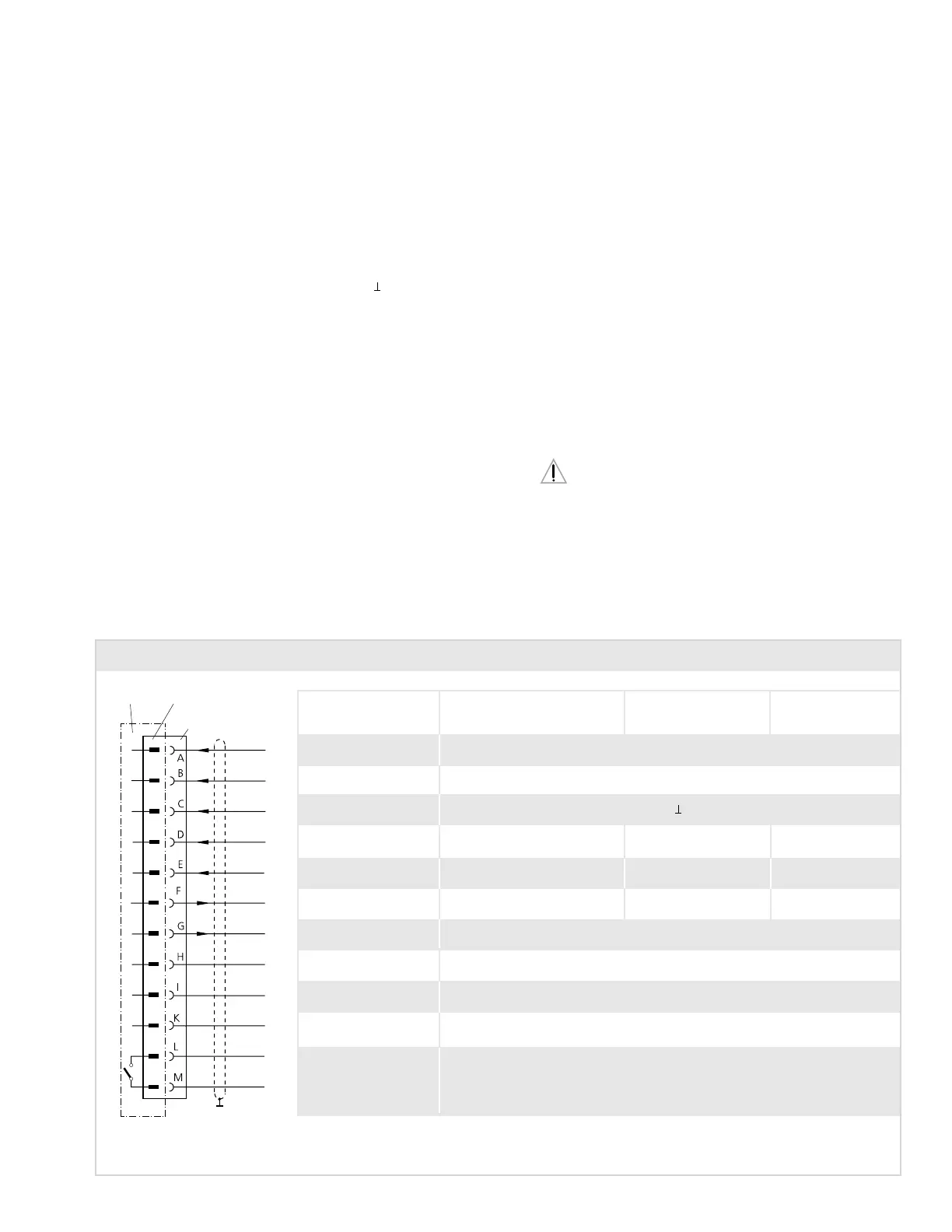
Valves with 12 pole bayonet connector to MIL C-26482/14-12. Mating connector: metal shell, Order-No.: B97027 012.
Function Voltage command Current command Current command
0 to ± 10 V 0 to ± 10 mA 4 to 20 mA
Supply + 15 VDC ± 3 %, ripple < 50 mV
PP
Supply – 15 VDC ± 3 %, ripple < 50 mV
PP
Supply / signal ground (0V)
Input rated command 0 to ± 10 V 0 to ± 10 mA 4 to 20 mA
Valve flow Input resistance 100 kΩ Load resistance 400 Ω Load resistance 200 Ω
Input invert. rated command 0 to ± 10 V 0 to ± 10 mA
Valve flow Input resistance 100 kΩ Load resistance 400 Ω
Output actual value 0 to ± 10 V 0 to ± 10 mA 4 to 20 mA
Spool position Output resistance 10 kΩ Load resistance max. 500 Ω Load resistance max. 500 Ω
Monitoring output of 0 to ± 12 V
internal position controller Output resistance 10 kΩ
Relay output
not used
not used
not used
not used
24 VDC, max. 0.5 A. For inductive loads a corresponding commutating diode is necessary.
The relay contact opens and the pilot stage is disconnected when supply voltage becomes less than
12 V (thus also in case of cable break). The spool then moves to the determind position without
electric supply. Cable break of the
⊥ wire is not monitored.
Valve Connector
Mating
connector
Cabinet side
Please note "General Requirements" on page 8.
Connector Wiring - Type code letter 0
9