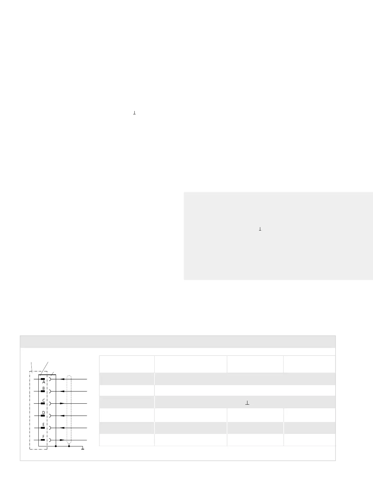
Connector Wiring - Type code 6
Valves with 6 pole connector to MIL C-5015/14S-6. Mating connector: metal shell, Order-No.: A26201 004
not used
Valve Connector
Mating
connector
Cabinet side
Function Voltage command Current command Current command
0 to ± 10 V 0 to ± 10 mA 4 to 20 mA
Supply + 15 VDC ± 3 %, ripple < 50 mV
PP
Supply – 15 VDC ± 3 %, ripple < 50 mV
PP
Supply / signal ground (0V)
Input rated command 0 to ± 10 V 0 to ± 10 mA 4 to 20 mA
Valve flow Input resistance 100 kΩ Load resistance 400 Ω Load resistance 200 Ω
Input invert. rated command 0 to ± 10 V 0 to ± 10 mA
Valve flow Input resistance 100 kΩ Load resistance 400 Ω
Output actual value 0 to ± 10 V 0 to ± 10 mA 4 to 20 mA
Spool position Output resistance 10 kΩ Load resistance max. 500 Ω Load resistance max. 500 Ω
Valve electronics with supply voltage
± 15 VDC and 6 pole connector
(without protective grounding)
a. Command input
Command signal 0 to
±10 V
The spool stroke of the valve is proportional to (U
D
– U
E
). 100% valve
opening P ➔ A and B ➔ T is achieved at (U
D
–U
E
) = +10 V. At 0 V
command the spool is in the center position.
The input stage is a differential amplifier. If only one command signal is
available, pin D or E is connected to signal ground (pin C) according
to the required operating direction (to be done at the mating connector).
Command signal 0 to
±10 mA
The spool stroke of the valve is proportional to (I
D
– I
E
).
100% valve opening P ➔ A and B ➔ T is achieved at (I
D
– I
E
)
= +10 mA. At 0 mA command the spool is in the center position.
Either pin D or E is used according to the required operating direction. The
unused pin is left open (not connected at the mating connector). The input
pins D and E are inverting.
Command signal 4 to 20 mA
The spool stroke of the valve is proportional (I
D
–12 mA). 100% valve
opeming P ➔ A and B ➔ T at I
D
= 20 mA.
At 12mA command the spool is in the center position.
The unused Pin E is left open (not connected in the mating connector).
General Requirements
➢ Supply ± 15 VDC ± 3%. Ripple < 50 mV
PP
. Current consumption max.
± 250 mA
➢ All signal lines, also those of external transducers, shielded
➢ Shielding connected radially to (0V)
➢ Note: When making electric connections to the valve (shield, protective
grounding), appropriate measures must be taken to ensure that locally
different earth potentials do not result in excessive ground currents.
b. Monitoring output
The actual spool position value can be measured at pin F.
This signal can be used for monitoring and fault detection purposes.
Command signal 0 to
±10 V
The spool stroke range corresponds to ±10 V.
+10 V corresponds to 100% valve opening P ➔ A and B ➔ T.
Command signal 0 to
±10 mA
The spool stroke range corresponds to ±10 mA.
+10 mA corresponds to 100% valve opening P ➔ A and B ➔ T.
Command signal 4 to 20 mA
The spool stroke range corresponds to 4 to 20 mA.
20 mA corresponds to 100% valve opening P ➔ A and B ➔
T.
8