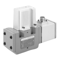
Electric supply
0 ± 15 VDC ± 3%
2 24 VDC (19 to 32 VDC)
Pilot stage
Pilot flow Pilot pressure
at p
X
= 140 bar p
X
A ServoJet 1.3 15 – 280
B ServoJet 2.0 15 – 280
F Nozzle/Flapper 1.15 15 – 280
G Nozzle/Flapper 0.65 15 – 280
Maximum operating pressure p
P
Pilot valve
B 70 bar. At p
X
≤ 70 bar (X and Y external) operating pressure A/B
in port P, A, B
and T up to 350 bar possible.
F 210 bar. At p
X
≤ 210 bar (X external) operating pressure A/B
in port P, A, B
and T up to 350 bar possible.
H 280 bar. At p
X
≤ 280 bar (X and Y external) operating pressure A/B
in port P, A, B
and T up to 350 bar possible.
K 350 bar (
with dropping orifice in filter cover) A/B, F/G
Valve version
P Standard spool
Model designation
assigned at the factory
Specification status
– Series specification
E Preseries specification
Z Special specification
Factory identification
Type designation
D661
Model-Number
Rated flow
Q
N
[l/min] at Dp
N
= 5 bar per land Valve version
16 16 P...F/G –
25 25 P...F/G –
30 30 – P...A/B
60 60 P...F/G P...A/B
80 80 – P...A/B
Main spool type
A 4-way: ~ critical lap, linear characteristic
D 4-way: 10 % overlap, linear characteristic
P 4-way: P ➔ A, A➔ T: ~ critical lap, curvilinear characteristic
P ➔ B: 60 % overlap, curvilinear characteristic
B ➔ T: 50 % underlap, linear characteristic
U 5-way: P ➔ A, P
2
➔ B, A ➔ T:~crit. lap, curvil. character.
Y 4-way: ~ critical lap, curvilinear characteristic
X Special spool on request
Options may increase price.
Technical changes are reserved.
Valve connector for supply voltage
S 6 + PE-pole DIN 43563 0 2
E 11 + PE-pole DIN 43651 — 2
*SV: Solenoid valve
**VE: Valve electronics
Spool position of main stage without electric or hydraulic supply
O undefined for all valve types
Mechanical failsafe
version
Position p
P
[bar] p
X
extern [bar]
AP ➔ B, A ➔ T ≥15 ≥15
M Mid position ≥15 <1
undefined ≥15 ≥15
R Mid position ≥15 <1
P ➔ B, A ➔ T ≥15 ≥15
L Mid position ≥15 <1
P ➔ A, B ➔ T ≥15 ≥15
Electrically controlled failsafe version
Position p
P
[bar] p
X
ext SV* VE**
W Mid position ≥15 ≥15 off on
Mid position ≥15 <1 on on
U Mid position ≥15 ≥15 off on
P ➔ B, A ➔ T ≥15 ≥15 on off (without electric supply)
VP ➔ B, A ➔ T ≥15 ≥15 off on
P ➔ B, A ➔ T ≥15 ≥15 on off (without electric supply)
P definiert ~30% ≥15 ≥15 off on (P
X
Torquemotor < 2 bar)
P ➔ B, A ➔ T ≥15 ≥15 on off
Signals for 100% spool stroke
Command Output for supply voltage
A ±10 VDC ±10 VDC 0 2 (11+PE diff)
B ±10 mA ±10 mA 0 —
C ±10 mA ±10 VDC — 2 (11+PE diff)
F ±10 VDC +2.5 to +13.5 V, enable — 2 (6+PE)
G ±10 mA +2.5 to +13.5 V, enable — 2 (6+PE)
T ±10 VDC ±10 V deadband comp. 0 2 (11+PE diff)
Seal material
N NBR Standard
V Fluorocarbon optional
Others on request
Pilot connections
Former code Supply Return
4 A, E, J internal internal
5 C, F, L external internal
6 B, G, K external external
7 D, H, M internal external
Preferred configurations are highlighted.
All combinations may not be available.
P
15

 Loading...