28
CALIBRATION POINTS (Continued)
PITCH OSCILLATOR TUNING
Two access points are provided for adjusting the Pitch Oscillators, and are located near the Pitch
Antenna. The two Pitch Oscillators are the Fixed Pitch Oscillator (FPO) and the Variable Pitch Oscillator
(VPO). The PITCH RANGE knob on the front panel changes the frequency of the Fixed Pitch Oscillator
by about 2 kHz. The Variable Pitch Oscillator is reduced in frequency as the right hand approaches
the Pitch Antenna. At the factory, it is adjusted for approximately a 5 kHz change in frequency from
when the right hand is away from the antenna to when it is touching the Pitch Antenna. When the
two oscillators are combined, the dierence between their respective frequencies is the signal you
hear. The original high frequency oscillator signals are filtered out of the audio signal in the process of
combining them. The Fixed Pitch Oscillator is tuned so it is at the same frequency as the Variable Pitch
Oscillator when the hand is away from the instrument. When the Fixed Pitch Oscillator and the Variable
Pitch Oscillator are at the same frequency, the dierence between them is zero; this is called “zero beat.”
Tuning the instrument with the PITCH RANGE knob sets the distance from the Pitch Antenna to
the zero beat point. The access point closest to the Pitch Antenna allows control of the VPO to
provide more or less pitch range. Before making any adjustments, be sure the PITCH RANGE knob
is at the center position. By turning the core of the variable inductor clockwise, the playing range is
reduced. Small adjustments can have a large eect. It is recommended to use about 1/8 of a turn at
a time to adjust, so that you do not get outside of the range of easy adjustment. As you adjust the
VPO inductor core clockwise to reduce the playing range, monitor the audio—you will hear the pitch
go up drastically. To return to a good playing state, turn the core of the centermost variable inductor
clockwise until you hear the pitch go down. When it gets about an octave below Middle C, stop turning
the core and try playing the instrument to test the range of playing. To increase the playing range, the
direction is reversed, and both inductor cores are turned counterclockwise.
NOTE: Proceed with caution! Too much range can lead to the resonance of the Pitch Antenna circuit matching the
frequency of the VPO, which can lead to unexpected extreme leaps in frequency and an unplayable instrument.
As always, do not attempt this adjustment if you are not fully confident in doing so or are unsure of the directions.
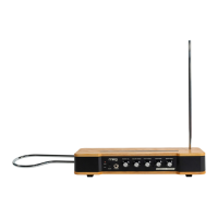
FRONT PANEL
The access point located between the PITCH RANGE
and WAVEFORM knobs allows control of a trimpot that
sets the bass response of your Etherwave Theremin. This
parameter is set at the factory so that a small amount of
coupling between the FPO and VPO occurs. This means
at zero beat, the oscillators are lightly locked together.
More coupling between the oscillators makes a stronger
zero beat, at the expense of the playability of the bass
register of the instrument. Less coupling makes the bass
register play smoother, but reduces the strength of zero
beat. The amount of coupling set at the factory may
cause the instrument to break out from the zero beat
state if the player walks away from the instrument
(in this case the MUTE button is a handy function).
Bass
Response
 Loading...