G761 SERIES INSTALLATION AND OPERATION INSTRUCTION
CDS6673 500-379 1199
Moog Inc., East Aurora, NY 14052-0018
Telephone: 716/655-3000
Fax: 716/655-1803
Toll Free: 1-800-272-MOOG
http://www.moog.com
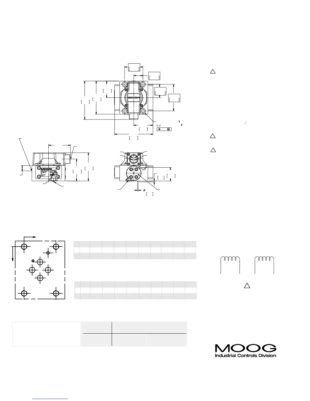
NOTES
TYPICAL WIRING SCHEMATIC
The products described herein are subject to change at any time without notice, including, but not limited to, product features, specifications, and designs.
1 Valve Weight:
2.4 lbs (1.08 kg) [4.0 lbs (1.81 kg)] for
steel body
2 Polarity:
A&C (+), B&D (-) produces flow out
port B
3 Manifold O-Rings
0.070 (1.78) sect x 0.426 (10.82) I.D.
(Universal dash No. 13)
4 Surface:
Surface to which valve is
mounted requires
32
( ) finish, flat
within .001 [0.03] TIR
5 Electrical Connector:
Mates with MS3106F14S-2S or equivalent
6 Null Adjust:
Flow out of port B will increase with
clockwise rotations of null adjust (3/32
hex key). Flow bias is continually varied
for a given port as the null adjust is
rotated.
7 Compressed Oil Volume
for one control port: 0.229 in3
(3.75 cm
3
)
8 Suggested Mounting Screws:
0.312-18 x 1.750 lg (M8 x 45)
socket head screw (4 req’d)
Dimensions in parenthesis are in millimeters.
U.S.
METRIC
Pilot flow Set screw bore
supply X (M4 X 6 DIN 912) P
Internal P closed open
External X open closed
CONVERSION INSTRUCTION
For operation with internal or
external pilot connection.
P
x

 Loading...


