D. USING BOTH 921B OSCILLATORS AND THE 921 VOLTAGE CON-
TROLLED OSCILLATOR
Control signals fed to the 921A OSCILLATOR DRIVER have the same effect on each 921B
OSCILLATOR. A control signal fed to a FREQUENCY control input jack raises and lowers
the frequencies of both 921B OSCILLATORS so the pitch interval between them remains
constant. A control signal fed to a WIDTH control input jack changes the width of the rectan-
gular waveforms of both 921B OSCILLATORS.
With the COARSE RANGE switch in the AUDIO position, the 921 VOLTAGE CON-
TROLLED OSCILLATOR is similar in operation to one 921A working in conjunction with
one 921B. The 921 can thus be used as an audio generator.
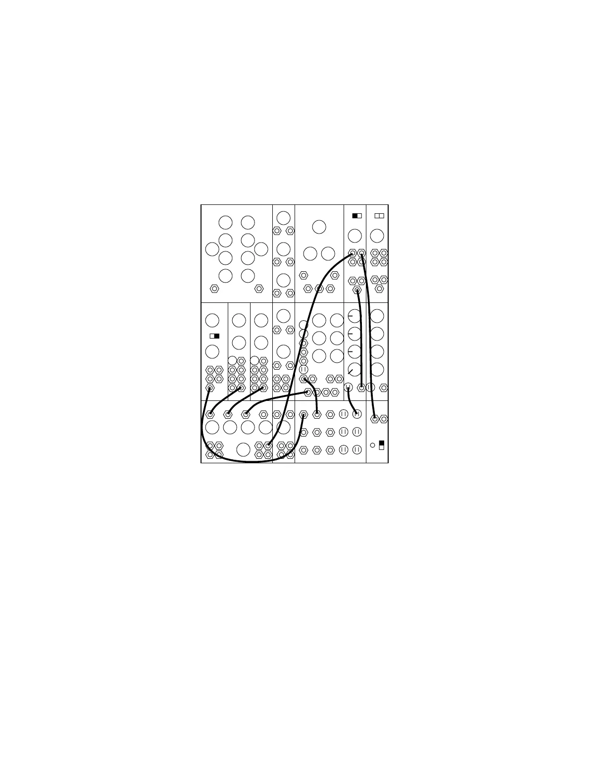
995 904A 902 902
921A 921B 923 921 911 911921B
MIXER REV CONTROLLERS TRUNK
907A
00
8’
50
6
0
16’
ABC
1. Clear the instrument. Arrange all patchcords and controls as shown above.
2. Turn up the panel MIXER controls A and B. Two tones should be heard, one ap-
proximately an octave above the other. Tuning is accomplished through the use of the FRE-
QUENCY controls and RANGE switches of either oscillator. The two waveforms generated
by the 921B OSCILLATORS are combined in the MIXER.
3. Play the keyboard. Notice that the interval stays constant while position on the keyboard
changes. The interval also remains constant with manual manipulation of the 921A FRE-
QUENCY control.
4. Turn up the MIXER control C. The third tone is produced by the 921 VOLTAGE CON-
TROLLED OSCILLATOR. The FREQUENCY, RANGE, and RECTANGULAR WIDTH
Controls all affect this third voice. The SCALE switch determines the amount of sweep of the
FREQUENCY control. All three oscillators will track. That is, the intervals between them re-
main constant as the keyboard is played.