14 | Dresser
Maintenance (cont’d)
Assembly
1. Disconnect control lines(s) and pilot supply line from pilot
system.
2. Loosen main spring case nuts in a crisscross pattern.
The main spring will lift the spring case as the nuts are
removed.
3. Remove spring, diaphragm/throttling element, spacer,
throttle plate and O-rings in that order.
4. Inspect all parts for wear and damage. Replace as
necessary.
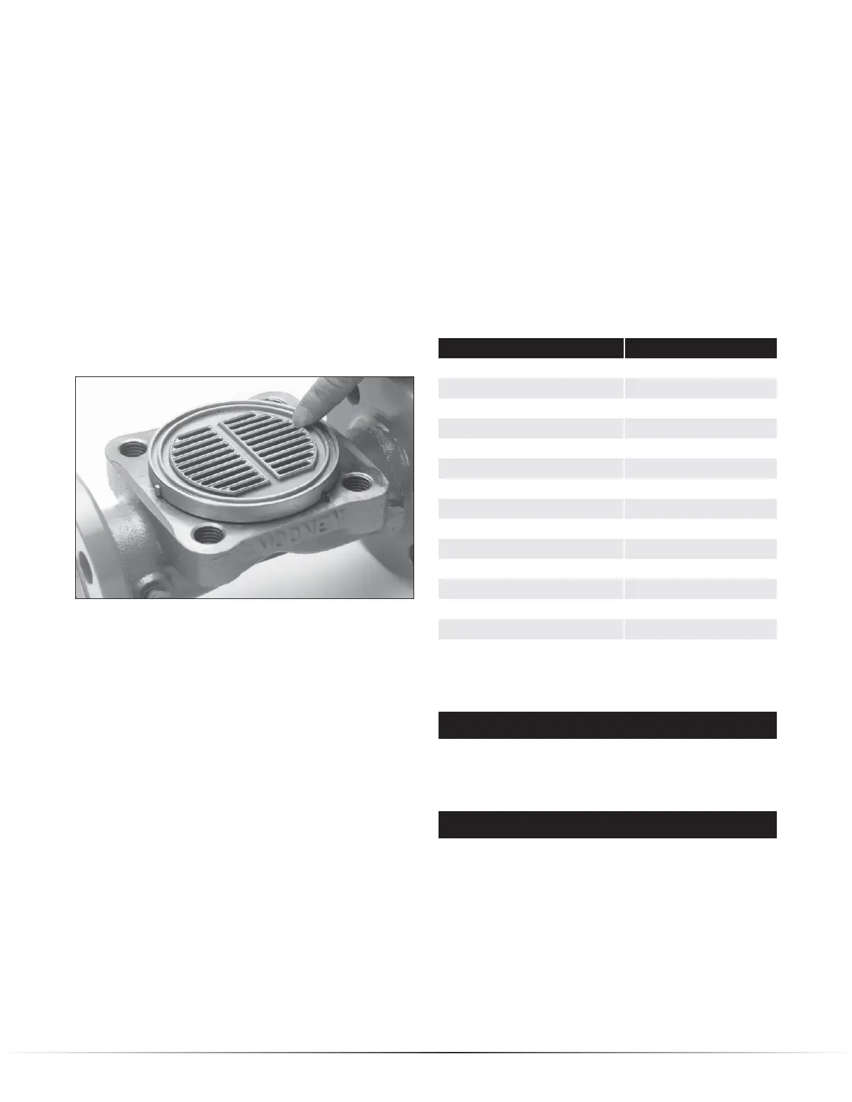
NOTE: The periphery of the downstream (outlet) portion
of the throttling plate is the primary shutoff surface and
should be inspected most closely for wear and damage.
Nicks and/or wear on the support ribs will usually not
affect shutoff.
The outside “rib” on the downstream side of the throttle plate is
where shutoff takes place in the Flowgrid
®
Valve.
NOTE: Nitrile O-rings can swell after disassembly of a
regulator that has been in service (due to gas permeating
the nitrile rubber). This does not necessarily mean they
must be replaced. Set O-ring aside for several hours
and it will gradually return to normal size. Placing the
O-ring(s) on ice will speed the process considerably.
Before placing the O-ring back into service inspect for
defects.
Cleaning
1. DO NOT clean O-ring grooves with sharp metal tools. The
bottom of the groove must have a smooth finish to prevent
leakage. The mating surface of adjacent parts must also
be smooth to prevent leakage.
Assembly
NOTE: Do not lubricate diaphragm sealing surface.
1. Reassemble parts on the body per the assembly drawing
in the parts supplement for the particular valve size.
NOTE: Both the throttle plate and the diaphragm can be
turned 180 degrees (not turned upside down) to renew
the shutoff capability if the inlet side is in better condi-
tion than the outlet.
2. Tighten main bolts in increments using a crisscross
pattern. Torque bolting as indicated on valve nameplate
(or refer to Table 4).
Bolting Torque Values
Clean Dry Bolts- Non-Lubricated
Valve Size Min. Torque Ft/Lbs
Flowgrid 250*** 20
1” (ALL)** 25
2’ x 1” (ALL)** 25
2” (ALL)** 60
3” (ALL)** 125
4” x 3” (ALL)** 125
4” (ALL)** 125
6” CL 150 & CL 300 Flanged 125
6” CL 600 Flanged 200
10” CL 150 & CL 300 Flanged 125
10” CL 600 Flanged 200
12” CL 150 & CL 300 Flanged 125
12” CL 600 Flanged 200
All Flowgrid Pilots 10
** Refer to WARNING below.
Table 5
WARNING
Lubricating and/or overtightening the bolting can
damage the Diaphragm in the 1” and 2” sizes of the
Flowgrid
®
valve.
WARNING
DO NOT replace the studs or nuts with any bolt or stud
and nut combination that does NOT have an SAE Grade
7 or ASTM Grade B7 rating.
3. Reconnect the pilot system. Follow Start up procedures
when returning to operation.
 Loading...