Flowgrid Regulator | 5
A back pressure regulator or relief valve controls upstream
pressure instead of downstream pressure. The control action
in the pilot is the reverse of a pilot for a pressure reducing valve
(increasing pressure in the sense chamber opens the pilot
valve). At no flow, when the inlet pressure is less than the set
point of the pilot regulator, the pilot is closed and full inlet pres-
sure loads the spring case through the pilot loading connection.
In this condition, the diaphragm is closed tightly against the
throttle plate. The pressure differential across the outlet half of
the diaphragm adds to the spring force in closing the Flowgrid
®
valve (Refer to figure 6).
As inlet pressure increases above the set point of the pilot
regulator, it will open and start bleeding pressure out of the
spring case faster than it can enter through the restrictor.
Reducing the pressure above the diaphragm allows inlet
pressure to progressively lift the throttling element off the throttle
plate opening the valve and satisfying the demand for flow in the
upstream system (Refer to Figure 7).
When upstream pressure decreases, causing the pilot regulator
to close, pilot supply pressure continues to pass through the
restrictor until the control pressure equals the inlet pressure.
The spring force, plus the pressure differential across the outlet
half of the throttling element closes the diaphragm against the
throttle plate, shutting off the flow (Refer to Figure 6).
Adjustment of the restrictor affects the response rate, stability,
and sensitivity of the regulator. Smaller restrictor openings result
in higher gain (sensitivity) and slower closing speeds. Larger
openings result in lower gain (greater proportional band), greater
stability and faster closing speeds.
Hydrostatic Testing
All Flowgrid
®
valves are hydrostatically tested at the factory
prior to shipment according to ISA-S75.19-1989 and
MSS-SP-61 standards. If it is necessary to retest the valve,
follow one of the procedures listed below to prevent damage
to the diaphragm.
OPTION 1
1. Disconnect and remove all control line(s) and the pilot
from the Flowgrid
®
Valve.
2. Loosen main spring case nuts in a crisscross pattern.
The main spring will lift the spring case as the nuts are
removed.
3. Remove main spring and diaphragm from valve.
FOR ALL 1”, 2”, 4”, AND 6” (AND 10”-V6)
FLOWGRID
®
VALVES
4. Replace diaphragm with a used diaphragm that has
the thick padded area cut out leaving the outer sealing
surface (see below).
This area removed
FOR 3” AND 4” x 3” FLOWGRID
®
VALVES
4. Remove diaphragm but leave diaphragm O-ring in place.
Make sure O-ring is properly seated.
5. Reassemble spring case on Flowgrid
®
valve.
6. Tighten main bolts in increments using a crisscross
pattern. Torque bolting as indicated on valve nameplate
(or refer to Table 5 Page 14).
7. Plug spring case loading port, pilot inlet and outlet taps
on Flowgrid
®
valve.
8. Refer to Table 3 for the maximum hydrostatic test
pressure of each Flowgrid
®
valve.
9. After hydrostatic test is completed follow the
Disassembly, Cleaning, and Assembly procedures in the
MAINTENANCE section of this manual.
OPTION 2
1. Disconnect and remove all control line(s) and pilot from
the Flowgrid
®
valve.
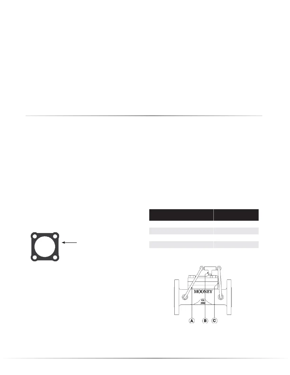
2. Pipe regulator with the inlet, outlet, and loading connec-
tions all common so that pressure is equalized in the
entire valve during the hydrostatic test. See Figure 8.
3. Refer to Table 3 for Maximum hydrostatic test pressure of
each Flowgrid
®
valve.
4. After hydrostatic test is completed follow the
Disassembly, Cleaning, and Assembly procedures in the
MAINTENANCE section of this manual.
End Connection Maximum Hydrostatic
Test Pressure (psi)
Screwed & Socket Weld 2225
150# Flange & Flangeless 450
300# Flange & Flangeless 1125
600# Flange & Flangeless 2225
Flowgrid 250*** 375
Maximum Hydrostatic Test Pressures
** The Flowgrid
®
250 is a ductile iron construction.
Table 3
Figure 8
A. Inlet connection on valve body joined to “Tee”.
B. “Tee” connected to loading connection on spring case.
C. Outlet of “Tee” connected to outlet connection on valve
 Loading...