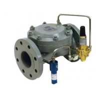
Piping Schematics
1. Single Port Regulator (PRV).
2. Single Port Regulator (BPV).
3. Dual Port Regulator/Single Pilot/(PRV).
4. Dual Port Regulator/Single Pilot/(BPV).
5. Dual Port Regulator/Dual Pilot/(PRV).
6. Dual Port Regulator/Dual Pilot/(BPV).
7. Standby Monitor with differential greater than 60 psig.
8. Standby Monitor with differential less than 60 psig.
9. Working Monitor.
All drawings show installations with the Series 20 Flowgrid
®
pilot equipped with Type 24 restricting valve & Type 30 Filter.
Consult factory for installation schematics of other manufac-
turer’s pilot on the Flowgrid
®
valve.
Flowgrid Regulator | 7
NOTE: The control line connection should be away
from areas of turbulence (such as valves, reducers, and
elbows) and should have a full opening into the pipe free
from burrs, drill peels, and weld slag. Shutoff valves are
not required in the control line(s), but if installed, they
should be of the full opening type.
12. PILOT discharge: Run 3/8 inch tubing from the pilot
OUTLET port to the downstream piping or to the connec-
tion provided on the outlet of the Flowgrid
®
valve as shown
in the piping schematics. (Refer to pages 7-11).
STANDBY MONITOR-NOTE: To ensure full capacity of
a Standby Monitor regulator station, it is important that the
pilot discharge of the upstream regulator be connected
downstream of the station if the minimum pressure drop
(across the entire station) is below 60 psig. (Refer to page
9 and page 12).
13. VENT VALVES AND GAUGE CONNECTIONS: Vent
valves and gauge connections are recommended in the
inlet and outlet piping to the Flowgrid
®
valve. A gauge
connection may be installed on the loading pressure
connection to the Spring Case of the Flowgrid® valve.
These would be a great convenience during start up,
maintenance, and operation.
14. INTERSTAGE PIPING (WORKING MONITOR):
On Working Monitor regulator stations the recommended
length of the interstage piping is 6 pipe diameters or
36-inches, whichever is greater. It is also recommended
that the interstage piping be swaged up 1 pipe diameter
over the nominal port size of the valve. (Refer to page 10).
FOR EXAMPLE:
1. If a station has two 3” Single Port Flowgrid
®
valves, the
interstage piping should be at least 36-inches in length
and swaging up to a 4-inch pipe.
2. If the station has two 2” x 1” Flowgrid
®
valves, (this valve
has two inch flanges with a one inch port) the interstage
piping should be at least 36-inches in length and a 2 inch
pipe diameter.
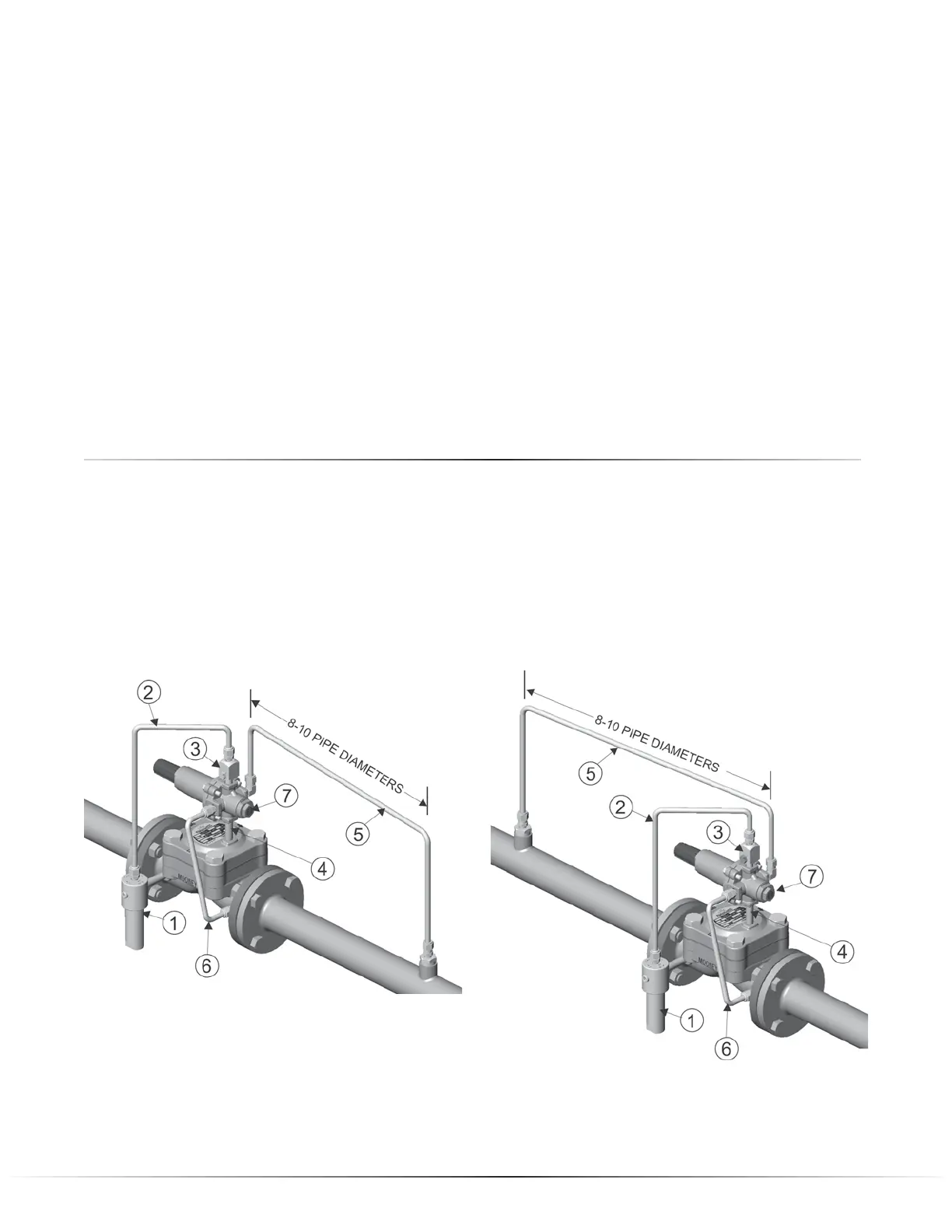
Single Regulator/ Single Pilot
(Pressure Reducing Valve)
Single Regulator/ Single Pilot
(Back Pressure Valve)
1. Filter supply connected from inlet connection on valve body to Type 30 Filter inlet.
2. Pilot supply from outlet connection on Type 30 Filter to Type 24 Restrictor inlet.
3. Type 24 Restrictor mounted to Inlet port of Series 20 Pilot.
4. Loading Port of Series 20 Pilot connected to Loading connection on Spring Case of Flowgrid
®
valve.
5. Sense line connecting Sense port on Series 20 Pilot to upstream (BPV) or downstream (PRV) piping.
6. Outlet port of Series 20 Pilot connected to Outlet connection of Flowgrid
®
valve.
7. Pilot cartridge in PRV mode (pressure reducing) BPV (back pressure / relief) mode.
 Loading...