Piping Schematics (cont.)
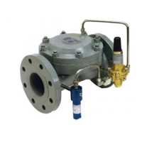
Dual Port/ Single Pilot (Pressure Reducing Valve)
Dual Port/Single Pilot (Back Pressure Valve)
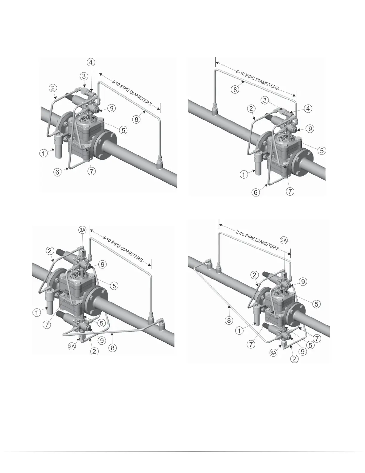
Dual Port/Dual Pilot (Pressure Reducing Valve)
NOTE: The dual port regulator offers redundant control with two separate control
loops. Ports #1 & #2 are piped identically.
Dual Port/Dual Pilot (Back Pressure Valve)
8 | Dresser
1. Filter supply connected from inlet connection on valve body to Type 30 Filter inlet.
2. Pilot supply from outlet connection on Type 30 Filter to Type 24 Restrictor inlet.
3. Type 24 Restrictor mounted to “Tee” connection.
3A. Type 24 Restrictor mounted to Inlet port of Series 20 Pilot.
4. Tee mounted to Inlet Port of Series 20 Pilot.
5. Loading Port of Series 20 Pilot connected to Loading connection on Spring Case (Port #1) of Flowgrid
®
Valve.
6. From “Tee” to Spring Case (Port #2) of Flowgrid
®
valve.
7. Outlet port of Series 20 Pilot connected to Outlet connection of Flowgrid
®
valve.
8. Sense line connecting Sense port on Series 20 Pilot to downstream (PRV) or upstream (BPV) piping
9. Pilot cartridge in PRV mode (pressure reducing) BPV (back pressure/relief) mode.