Piping Schematics (cont.)
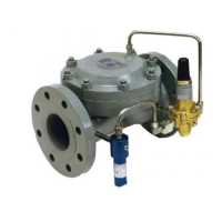
Standby Monitor with Differential Pressure Greater than 60 psi
Operating Regulator
Monitor Regulator
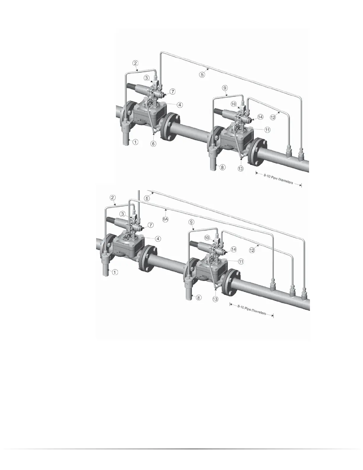
Standby Monitor with Differential Pressure Less than 60 psi
Operating Regulator
Monitor Regulator
Flowgrid Regulator | 9
1. Filter supply connected from inlet connection on valve body to Type 30 Filter inlet.
2. Pilot supply from outlet connection on Type 30 Filter to Type 24 Restrictor inlet.
3. Type 24 Restrictor mounted to Inlet port of Series 20 Pilot.
4. Loading Port of Series 20 Pilot connected to Loading connection on Spring Case of Flowgrid
®
valve.
5. Sense line connecting Sense port on Series 20 Pilot to downstream piping.
6. Outlet port of Series 20 Pilot connected to Outlet connection of Flowgrid
®
valve.
6A. Outlet port of Series 20 Pilot connected to downstream piping.
7. Pilot cartridge in PRV mode.
8. Pilot supply from inlet connection on valve body to Type 30 Filter inlet.
9. Pilot supply from outlet connection on Type 30 Filter to Type 24 Restrictor inlet.
10. Type 24 Restrictor mounted to Inlet port of Series 20 Pilot.
11. Loading Port of Series 20 Pilot connected to Loading connection on Spring Case of Flowgrid
®
valve.
12. Sense line connecting Sense port on Series 20 Pilot to downstream piping.
13. Outlet port of Series 20 Pilot connected to Outlet connection of Flowgrid
®
valve.
14. Pilot cartridge in PRV mode.