2nd Stage Regulator
1st Stage Regulator
Pilot #1
Pilot #2
10 | Dresser
1st Stage Regulator
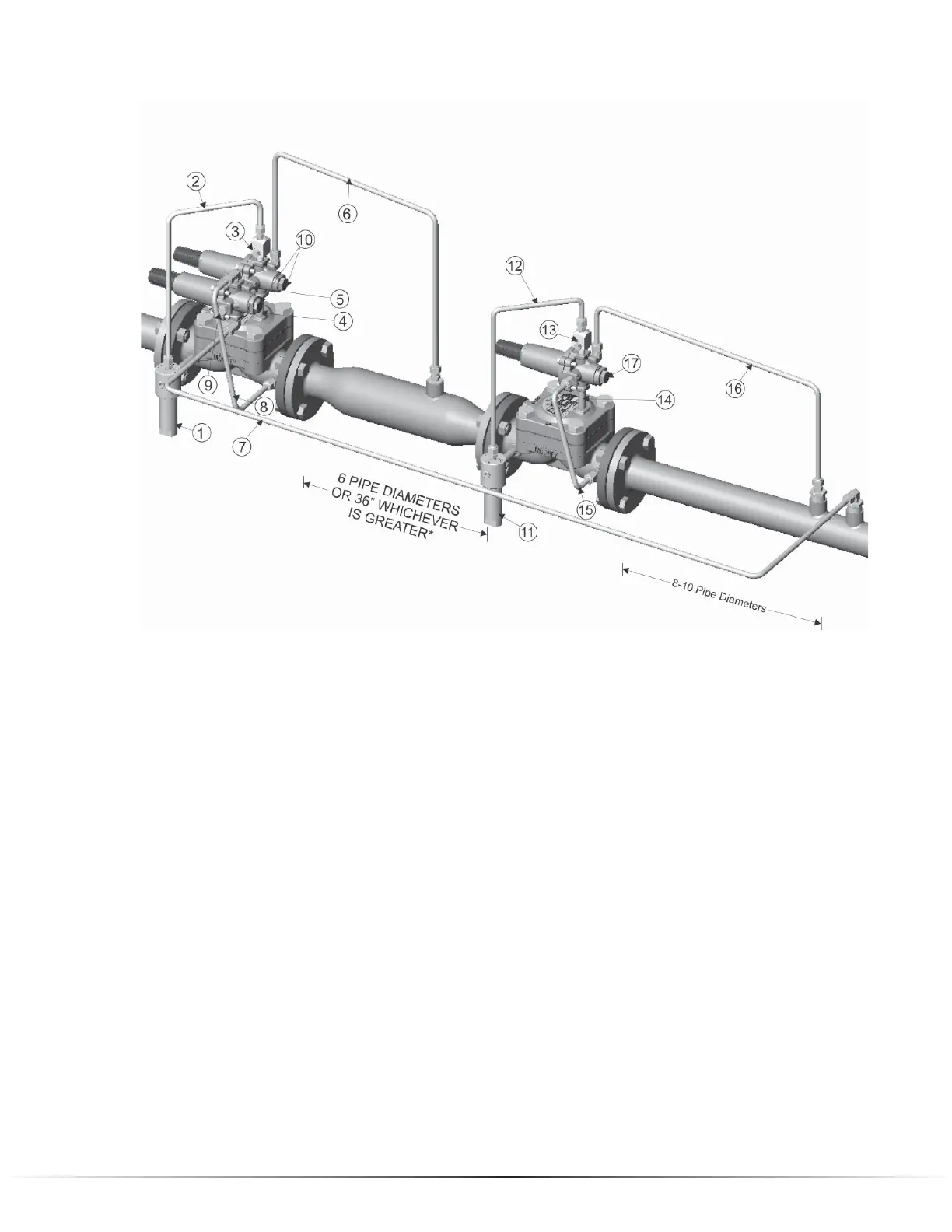
1. Filter supply connected from inlet connection on valve body to Type 30 Filter inlet.
2. Pilot supply from outlet connection on Type 30 Filter to Type 24 Restrictor inlet.
3. Type 24 Restrictor mounted to Inlet port of Series 20 Pilot (#1).
4. Loading Port of Series 20 Pilot (#1) connected to Loading connection on Spring Case of the
Flowgrid
®
valve.
5. Outlet port of Series 20 Pilot (#1) connected to Inlet port of the monitor Series 20 Pilot (#2).
6. Sense line connecting sense port on Series 20 Pilot to interstage piping.
7. Sense line connecting sense port on the monitor Series 20 Pilot (#2) to downstream piping.
8. Outlet port of Series 20 Pilot (#2) connected to Outlet connection of Flowgrid® valve.
9. Loading port on the monitor Series 20 pilot (#2) is plugged.
10. Pilot cartridges in PRV mode.
2nd Stage Regulator
11. Filter supply connected from inlet connection on valve body to Type 30 Filter inlet.
12. Pilot supply from outlet connection on Type 30 Filter to Type 24 Restrictor inlet.
11. Pilot supply tubing from inlet connection on valve body to Type 24 Restrictor inlet.
13. Type 24 Restrictor mounted to Inlet port of Series 20 Pilot (#3).
14. Loading Port of Series 20 Pilot (#3) connected to Loading connection on Spring Case of the
Flowgrid
®
valve.
15. Outlet port of Series 20 Pilot (#3) connected to Outlet connection of Flowgrid
®
valve.
16. Sense line connecting Sense port on Series 20 Pilot (#3) to downstream piping.
17. Pilot (#3) cartridge in PRV mode.
NOTE: In a working Monitor system with less than 25 psig differential across the second stage
regulator the pilot supply (11) may be connected to the piping upstream of the first stage regulator.
This will improve the shutoff of the second stage regulator.
Piping Schematics (cont.)
Working Monitor (Refer to schematic on page 14)