MOONEY INTERNATIONAL CORPORATION
M20V SERVICE AND MAINTENANCE MANUAL
Page
Date
8
MAR 2017
Rev Date
12-20-05 - HYDRAULIC BRAKES (Bleeding)
-CAUTION-
Fluid in the wheel cylinders may be under
high pressure due to heat or expansion.
Therefore, be sure parking brake is released
prior to beginning hydraulic system servic-
ing. For best results, use a hydraulic pres-
sure service unit (pressure pot) to back bleed
the system through wheel cylinder bleeder
valves.
-NOTE-
Brake pedal may need to be pulled back in order
for fluid to bleed back into reservoir.
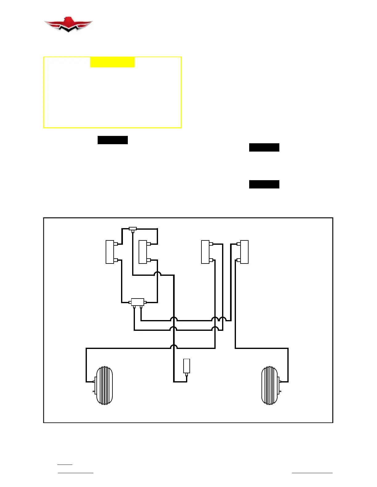
DUAL BRAKE SYSTEM (Ref. Figure 12- 2)
1. Remove hydraulic fluid reservoir filler plug, and
install a suitable fitting for attaching a flexible drain line.
2. Immerse open end of drain line into a hydraulic
fluid container or catch container containing
MIL-H-5606 fluid.
3. Attach pressurized hydraulic fluid service unit to
wheel cylinder bleeder valve and open valve. Hydraulic
service unit should be free of air prior to servicing air-
craft system.
4. Feed fluid from service unit into brake system.
Check for air bubbles at end of drain line immersed in
fluid.
5. When fluid is flowing, slowly depress co-pilot’s
brake pedal by hand and slowly release. Repeat three
(3) to four (4) times.
6. Allow fluid to flow until clear of air bubbles.
7. Close wheel cylinder bleeder valve; remove ser-
vice line.
-NOTE-
Brake pedal may need to be p ulled back in order
for fluid to bleed back into reservoir.
8. To bleed opposite brake, repeat steps 3 through 7.
-NOTE-
If brake pedal is still soft or spongy, you can try
to hang each master cylinder vertical, bleed sys-
tem again using the pressure pot method.
PILOT
RESERVOIR
WHEELWHEEL
PARKING
BRAKE
CO-PILOT
A
B
C
D
AC
DUAL BRAKE INSTALLATION
HYDRAULIC BRAKE SYSTEM SCHEMATICS
FIGURE 12- 2
12-20-05
 Loading...


