MOONEY INTERNATIONAL CORPORATION
M20V SERVICE AND MAINTENANCE MANUAL
Page
Date
5
MAR 2017
Rev Date
21-00-00 - CABIN VENTILATION SYSTEM
The cabin environmental system consists of three
standard ventilating systems that supply heated or
fresh air as the pilot or passengers prefer. FRESH AIR,
CABIN VENT and OVERHEAD VENTILATION. The
cabin air and heat system controls and vents are lo-
cated on the console between the pilot and co- pilot
seats. Individual fresh air outlets are located on each
side of the cabin side panels just forward of the pilots
and co- pilots outboard knees. The overhead ventila-
tion system consists of individual outlets (Wemac
valves) located between and above each seat position.
The aircraft has a flow regulator system with the control
knob located above and between the pilot’s and co- pi-
lot’s head. The systems are basically trouble free but
inspection should be made at regular intervals to en-
sure proper operation.
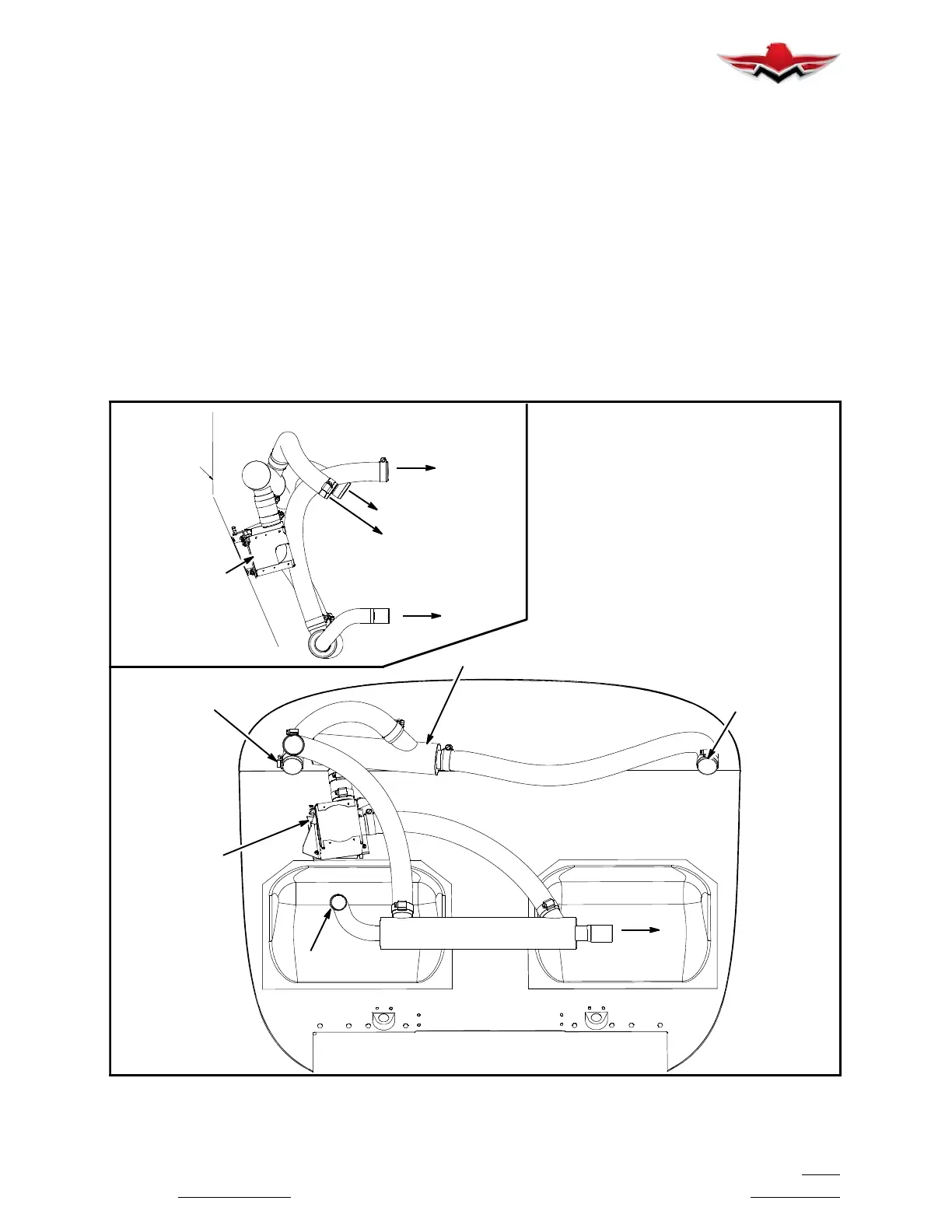
21-40-00 - HEATING
Heat is extracted from the high pressure/temperature
flow between the compressor and intercooler through
flexible hoses connecting the turbocharger air induc-
tion pipes (Fig. 21- 1) and the cabin heater box assem-
bly. The air from the high pressure/temperature flow is
regulated by fixed orifice sonic nozzles. It is recom-
mended that the condition of the flexible hoses, clamps
and cabin heater box be checked each time the cowling
is removed. Any deteriorated flexible hoses/ducts
should be replaced. It is recommended that inspection
of the exhaust system for any leaks or cracks, at each
maintenance action, be made and replace compo-
nents or repair as needed. This will provide a continu-
ing check for the prevention of carbon monoxide (CO)
in the cabin.
HEATER
BOX
ASSY.
FIREWALL
TO RH NOZZLE
TO LH NOZZLE
HEATER
BOX
ASSY.
HEAT SHROUD ASSY
SILENCER
TO WASTEGATE
TO RH EXHAUST
TO BAFFLE PORT
TO LH NOZZLE
TO RH NOZZLE
TO RH EXHAUST
SIDE VIEW
RH
FIREWALL
LH SIDERH SIDE
HEATER BOX AIR DUCTING
FIGURE 21- 1
21-00-00
 Loading...


