MOONEY INTERNATIONAL CORPORATION
M20V SERVICE AND MAINTENANCE MANUAL
Page
Date
8
MAR 2017
Rev Date
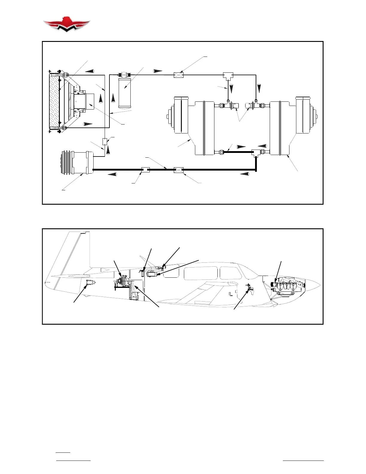
HOSE
~
DRYER/
PRESSURE
SWITCH
HAT RACK
BULKHEAD
CONDENSER
EXPANSION
VALVE
EVAPORATOR
FAN/MOTOR
COMPRESSOR
FIREWALL
BULKHEAD
HAT RACK
BULKHEAD
EVAPORATOR
FIREWALL
BULKHEAD
TUBE TUBE
TUBE
TUBE
TUBE
HOSE
HOSE
HOSE
HOSE
HOSE
PLUMBING SCHEMATIC – AIR CONDITIONING SYSTEM (TYP.)
FIGURE 21- 3
CONDENSER
INSTALLATION
DRYER
ASSEMBLY
DUCT
ASSEMBLY
EVAPORATOR INSTALLATION
SWITCH
INSTALLATION
EXHAUST
DUCT
AIR
INLET
COMPRESSOR
INSTALLATION
AIR CONDITIONING COMPONENT LOCATIONS
FIGURE 21- 4
21-51-01 - SPECIAL TOOLS AND/OR
EQUIPMENT REQUIRED
The following tools and/or equipment are required to
leak check a refrigerant plumbing system.
1. Gaseous dry nitrogen, regulated source (0- 500
PSIG)
2. R-134a refrigerant charging manifold with gauges
and hoses
3. Electronic leak detector
4. R-134a refrigerant, 30 lb. cylinder
5. R-134a Refrigerant oil, (Ester RL- 500S)
6. Leak check fluid, (soapy solution)
7. Assorted hand tools
8. Hand and eye protection
9. Thread sealant, P/N 554 (Loctite)
10. Hose adapter (1/2 in. male acme to 1/4 in. female
flare)
21-51-02 - LEAK CHECK PROCEDURE
The system must be evacuated prior to Leak Check
Procedure. See Section 21-52-02.
1. Remove, if required, all panels, doors, shrouds,
etc. to gain access to component being leak checked.
21-51-01
 Loading...


