MOONEY INTERNATIONAL CORPORATION
M20V SERVICE AND MAINTENANCE MANUAL
Page
Date
11
MAR 2017
Rev Date
7. Move aircraft to run- up area.
8. Start aircraft engine. Select ”MAX” on air condi-
tioner switch. Idle aircraft engine at 1200- 1800 RPM.
Verify Alternator is charging.
-CAUTION-
Do not operate system with high pressure
(RED) valve open on the charging manifold
gauge set.
9. With system operating, observe the system dis-
charge and suction pressure values and refrigerant
condition in the receiver- dryer sight glass.
-NOTE-
A flashlight and inspection mirror are required to
observe sight glass during the system charging
procedure. Excessive bubbles in the sight glass
indicate a low refrigerant level.
10. With the R- 134a cylinder connected to the
charging hose, charging container shutoff valve open
and hose purged, slowly open the suction manifold
valve (BLUE). The suction pressure will increase to
60- 70 PSIG while the R- 134a refrigerant enters the
compressor.
-NOTE-
As refrigerant enters the compressor, a slight
increase in discharge pressure will be noted
(2- 5 PSIG).
11. Continue to add refrigerant per the above proce-
dure until the sight glass is clear of excessive bubbles
when charged on a hot day (95- 105
o
F).
-NOTE-
A desired sight glass liquid condition is when
only occasional bubbles are observed when
charging on a hot day (95- 105
o
F).
12. Close suction manifold valve (BLUE) and let sys-
tem operate for 5- 10 minutes and then check sight
glass. If sight glass is not totally clear, open suction
manifold valve and add a small quantity of refrigerant
until 98% of bubbles disappear. Close manifold valve
and let system stabilize.
-NOTE-
Letting the system stabilize is required since the
expansion valve is trying to stabilize to the pre-
set suction pressure value.
-CAUTION-
Do not overcharge system or component and
system damage may occur. Full system
charge is approximately 2.2 lbs. of R-134a.
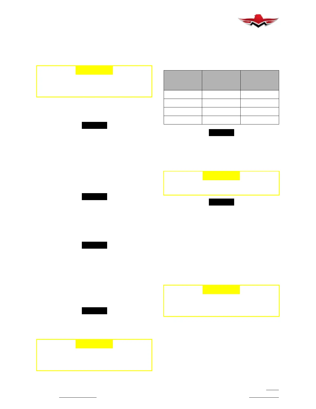
13. With the system fully charged and operating, ob-
serve the suction and discharge pressures shown in
the following chart.
Typical values at various ambient temperatures, with
hot cabins, are shown in the following chart:
O.A.T. (
o
F)
SUCTION
PRESSURE
(PSIG)
DISCHARGE
PRESSURE
(PSIG)
60- 70 28 125- 140
80 30 170 +/- 10
95 31 210 +/- 10
105 32 237 +/- 10
-NOTE-
Whenever possible, the system should be
charged on a hot day (90- 100
o
F). If not, ”topping
off” may be required for ambient conditions.
14. Allow system to operate for 10 minutes and then
shutdown.
-CAUTION-
Do not allow aircraft engine temperatures to
exceed limits.
-NOTE-
After shutdown, both suction and discharge
pressures will begin to equalize. Pressures
should be equal in 60 - 90 seconds.
15. Close refrigerant container shutoff valve (turn
C/W). Record the refrigerant container final weight and
calculate system refrigerant charge as follows:
CHARGE (lb.) = W initial (lb.) - W final (lb.)
16. Turn knob on suction and discharge charging
hose quick coupler to closed position and disconnect
hoses from service ports.
17. Remove YELLOW charging hose from refriger-
ant container and store manifold gauge set.
-CAUTION-
Hand and eye protection must be worn dur-
ing this operation to prevent subcooled re-
frigerant from burning eyes or hands.
21-53-00 - EXPANSION VALVE ADJUSTMENT
PROCEDURE
Even though the automatic expansion valves are set by
the manufacturer there may be times when it must be
adjusted to assure proper refrigerant flow. Any adjust-
ment must not affect system suction and compressor
discharge pressures as outlined in Section 21-52-03,
13. Changing expansion valve settings will also
change evaporator air output temperatures.
21-53-00
 Loading...


