MOONEY INTERNATIONAL CORPORATION
M20V SERVICE AND MAINTENANCE MANUAL
Page
Date
13
MAR 2017
Rev Date
19. Replace all shrouds, covers and enclosures re-
movedinstep2.
21-54-00 - COMPRESSOR DRIVE BELT
INSPECTION & MAINTENANCE PROCEDURE
When the compressor drive belt requires removal and
replacement, tension or alignment, the following proce-
dures will apply:
21-54-01 - BELT REMOVAL PROCEDURE
1. Verify all aircraft or ground power is OFF.
2. Remove cowling to gain access to the compres-
sor.
3. Loosen jam nut on adjusting bolt of idler pulley.
4. Loosen slide nut slightly to allow slide to move up
and down.
5. Turn adjusting nut out far enough to allow belt re-
moval.
6. Remove belt from all three pulleys.
-CAUTION-
Do not bend or twist the drive belt excessive-
ly during removal or damage may result.
7. Inspect belt for cracks or damage and clean any oil
or other contamination from all pulleys and belt.
21-54-02 - DRIVE BELT REPLACEMENT
PROCEDURE
1. Verify belt size and part number (see Illustrated
Parts Catalog) before installing or damage may result.
2. Place new belt, or inspected and cleaned belt,
over compressor pulley, idler pulley, and drive pulley.
-CAUTION-
During this procedure, do not sharply bend or
twist belt and do not allow belt to rotate on
drive pulley flange. Damage to belt may
result.
3. After belt is installed, rotate the compressor pulley
clockwise (CW) to align belt on pulley. Belt MUST align
directly over the compressor pulley. MAGNETO
SWITCH - OFF.
-NOTE-
If belt is too far forward or aft on the compressor
pulley, the idler pulley and drive pulley MUST be
adjusted forward or aft to allow belt to align di-
rectly over compressor pulley. See Section
21-54-03 for alignment procedures.
4. If belt alignment is GOOD, install belt guard (if re-
moved) and tighten the two compressor mounting bolt
nuts. Proceed to 21-54-04.
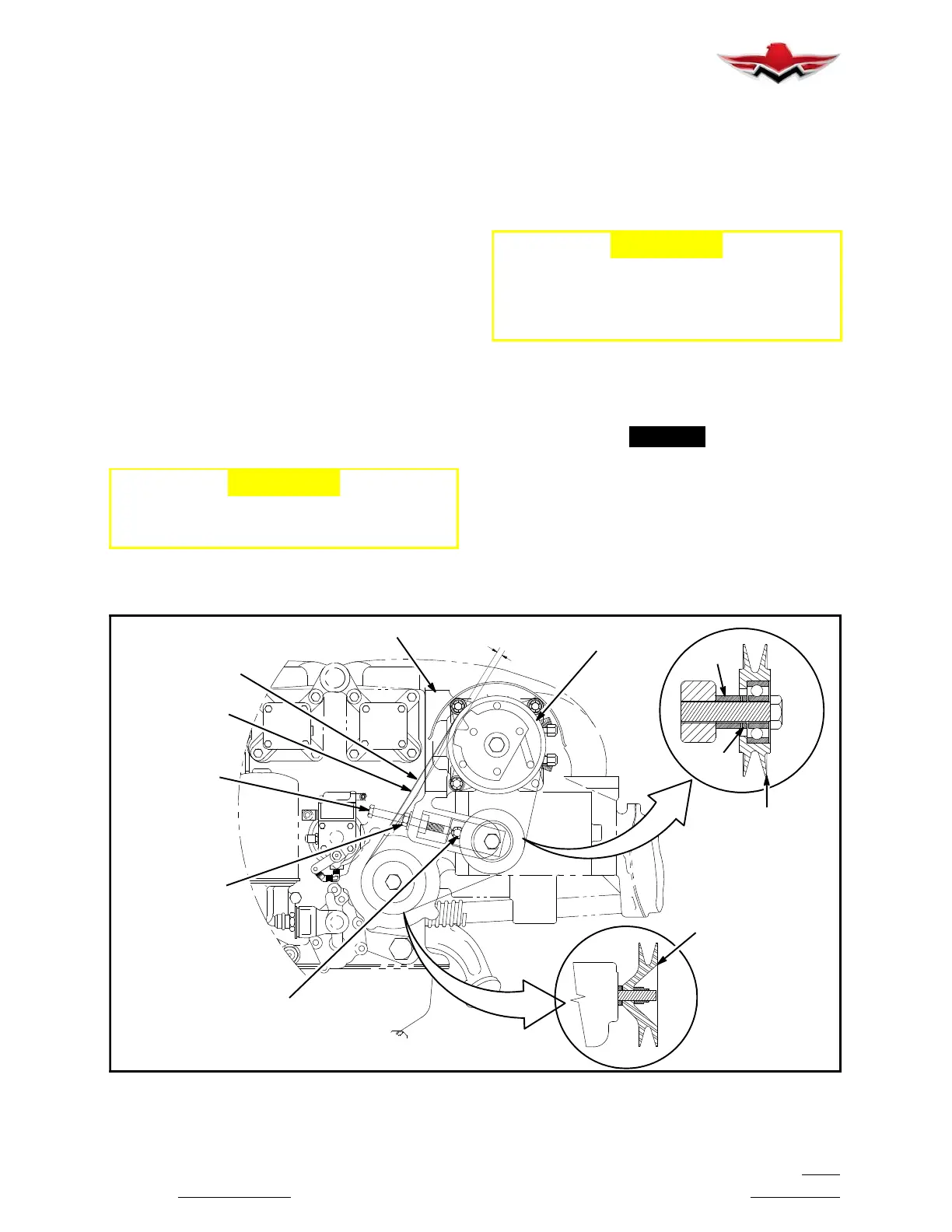
LOOKING FWD
BRACKET ASSEMBLY
V-BELT
JAM NUT &
TENSION
ADJUSTING
DRIVER SHEAVE
(REF)
CHECK MIDSPAN
DEFLECTION HERE
FREON COMPRESSOR
IDLER PULLEY SLIDE ADJUSTMENT
BOLT, WASHER & NUT
IDLER SHEAVE
0.3 - 0.4 IN.
VIEW
ASSEMBLY
WASHER
BOLT
SHIM
SPACER
DRIVE BELT TENSIONING
FIGURE 21- 5
21-54-00
 Loading...


