MOONEY INTERNATIONAL CORPORATION
M20V SERVICE AND MAINTENANCE MANUAL
Page
Date
7
Rev Date
MAR 2017
22-10-00 GARMIN GFC700 AUTOPILOT SERVOS
AND SERVO MOUNTS
The GSA 8(X) Servo is mated to the GSM 86 Servo
Mount to form a single servo unit. The design of the
servo a ssembly allows the servo portion to be re-
moved from the servo mount without the need to re -
rig the aircraft control c ables. The M20V aircraft is
equipped with 3 servos and servo mounts.
The GSM 86 servo gear box clutch is available in
three torque sizes (short, medium, and long), for
each of the available mechanical interface configur-
ations (spiral, continuous, and sprocket, etc.), with
torque ranges defined by Table below:
1. Short Clutch: 15- 65 in- lbs 15% P/N
383- 00000- 15 thru 383- 00000- 65
2. Medium Clutch: 66- 120 in- lbs 15% P/N
383- 00000- 66 thru 383- 00001- 20
3. Long Clutch: 121- 180 in- lbs 15% P/N
383- 00001- 21 thru 383- 00001- 80
22-10-01 ROLL SERVO AND SERVO MOUNT
1. Removal of Roll Servo P/N 011-00878-20
A.
Ensure aircraft power is off. Unplug any auxil-
iary power supplies.
B. Remove the forward belly fairing.
C. Set the ailerons in neutral position and insert
aileron rig pin.
D. Remove the middle and side panels of the
center console to access roll servo.
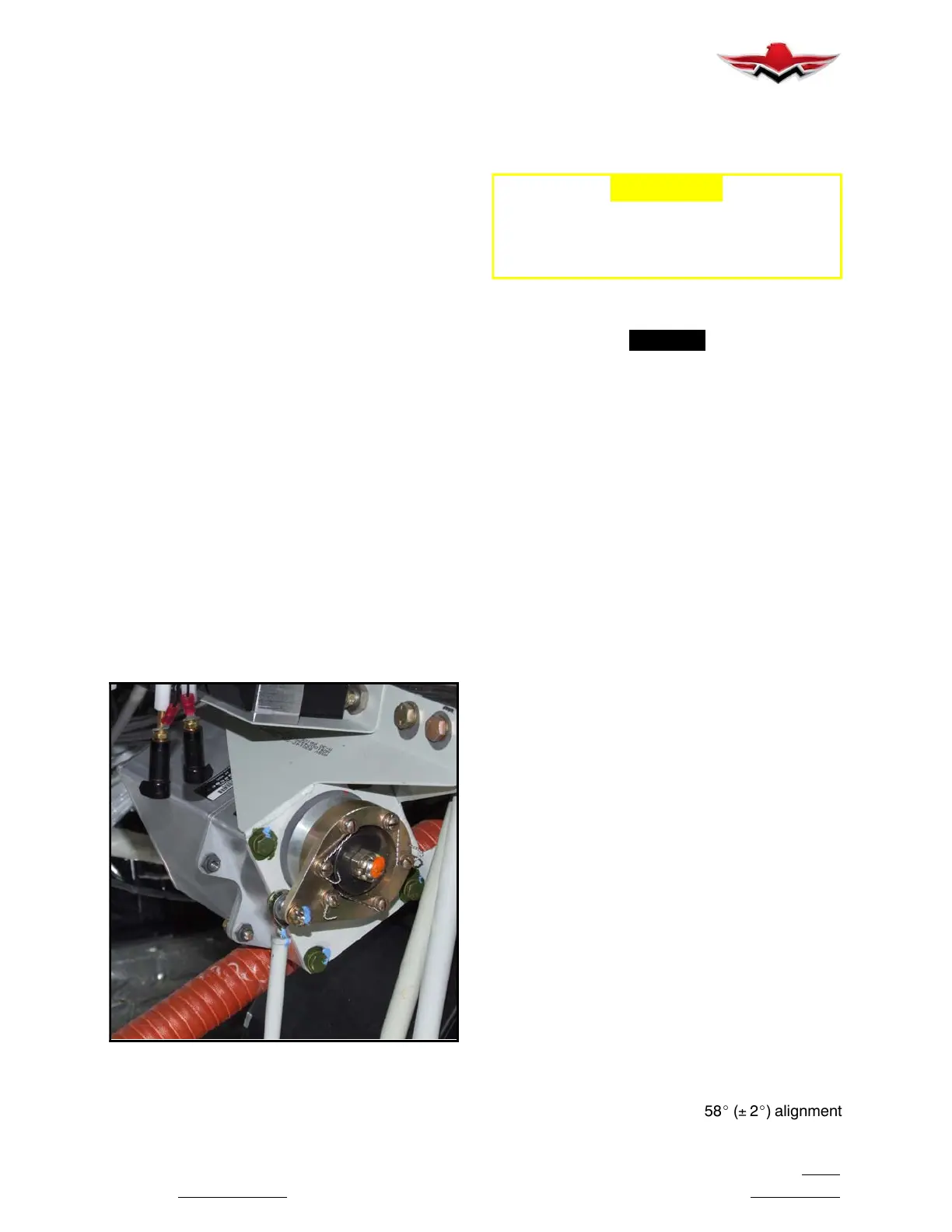
ROLL SERVO MOUNTING
FIGURE 22- 2
E.
Disconnect servo pigtail connector.
F. Remove the (2) mounting bolts from roll servo
to roll servo mount.
G. Remove the unit.
-CAUTION-
USE CARE WHEN REMOVING SERVO
MOUNT FROM AIRCRAFT NOT TO ALLOW
ANY FOREIGN OBJECT DEBRIS TO ENTER
SERVO MOUNT ORIFICES (CLUTCH ASSY).
H.
Remove excess grease b uild- up from the
single servo output gear using a lint- free cloth.
-NOTE-
It is not necessary to remove all of the grease
from the output gear, only the excess grease. DO
NOT USE SOLVENTS TO CLEAN THE OUTPUT
GEAR.
2. Removal of Roll Servo Mount
P/N 011-01904-00
A.
Remove the center cotter pin and retaining
nut holding the roll servo mount arm.
B. Remove the safety wire (MS20995-C) and (6)
mounting screws and washers holding the roll servo
mount arm. Roll servo mount arm should be free to
remove.
C. Remove the (4) mounting bolts holding the
roll servo mount to the bracket. Remove servo
mount.
3. Roll Servo Mount Clutch Adjustment
A.
For instructions on checking the slip- clutch,
refer to the GSM Slip- Clutch Setting Procedure in
the GSA 8X/GSM 86 Installation Manual (Garmin
part number 190- 00303- 83 or later revision). To de-
termine the slip- clutch torque setting refer to Figure
22- 9. If a slip clutch is found to be out of spec, it
should be replaced with a new slip clutch. GSM 86
slip clutches are not settable once manufactured.
4. Installation of Roll Servo and Roll Servo Mount
A.
Install roll servo mount (GSM86) to bracket
with original (4) bolts. Refer Figure 22- 9 Torque
Chart for Specifications (Clutch Kit 011-02147-12).
B. Use a brush or applicator, apply a thin coat of
grease to the servo output gear. Use Aeroshell
33MS or Aeroshell 17. Clean and apply grease to
output gear every 1000 hours or 3 years.
C. Install roll servo to roll servo mount with origi-
nal (2) bolts (see Figure 22- 3). Refer Figure 22- 9
Torque Chart for Specifications.
D. With ailerons in neutral position install servo
mount arm with (6) mounting screws and washers.
Install center nut, washer and new cotter pin. Adjust
rod end on the servo control rod as needed (lengthen
or shorten) to obtain the proper 58_ ( 2_) alignment
22-10-00
 Loading...


