MOONEY INTERNATIONAL CORPORATION
M20V SERVICE AND MAINTENANCE MANUAL
Page
Date
13
Rev Date
MAR 2017
22-10-05 FLAP POSITION DISCRETE INPUT
CHECK
Also refer to the G1000 Line Maintenance and Con-
figuration Manual (#190- 00303- 04 Rev F and In-
structions for Continued Airworthiness
#190- 00638- 002 Rev A or later FAA approved revi-
sions).
To perform this check, all G1000 and GFC 700
equipment must be installed and operational. Start
the G1000 system in Configuration Mode and go to
the GIA Page Group and select the GIA I/O Configu-
ration Page using the FMS knob. Perform the follow-
ing checks:
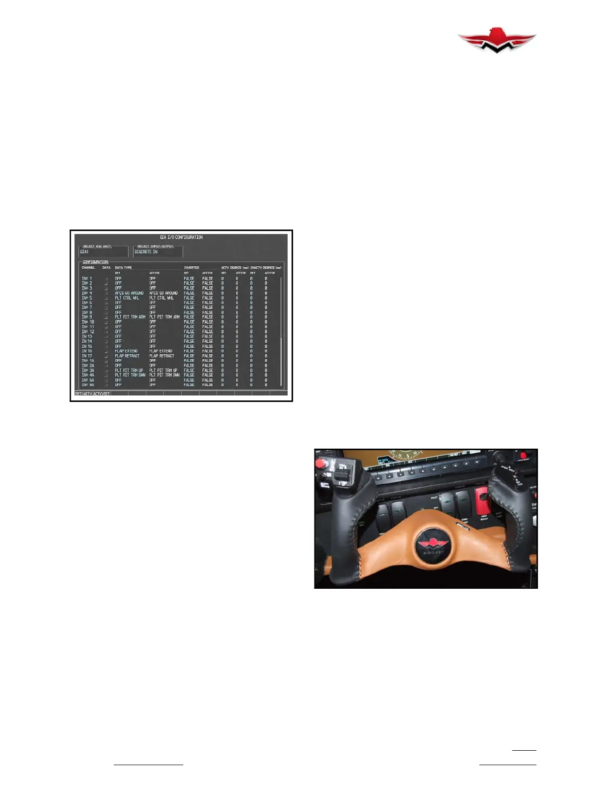
FIGURE 22- 11. GIA I/O Page
1.
Extend the flaps down. While the flaps are
transitioning down, check that the discrete input la-
beled “FLAP EXTEND” lights up green.
2. Retract the flaps u p. While the flaps are transi-
tioning up, check that the discrete input labeled
“FLAP RETRACT” lights up green.
3. Restart the G1000 system in normal mode.
Wait until the AHRS and ADC systems come online
and for the AFCS Pre- flight Test to complete.
4. Press the FD key on the MFD to engage the
Flight Director. Press the AP key to engage the Auto-
pilot. Press the CWS button for a few seconds and
release; verifying there is no residual force on the
control wheel for the pitch axis. Extend the flaps to
approach position. The trim wheel should immedi-
ately run in the UP direction. Now retract the flaps.
The trim should immediately run in the DOWN direc-
tion.
5. The flap discrete input check is complete.
22-20-00 TROUBLESHOOTING
Troubleshooting the GFC 700 system per the G1000
Line Maintenance and Configuration Manual
(#190- 00303- 04 Rev F or later FAA approved revi-
sion).
22-20-01 LRU REPLACEMENT PROCEDURES
Installing the LRU per procedures in the G1000 Line
Maintenance and Configuration Manual
(#190- 00303- 04 Rev F or later FAA approved revi-
sion).
22-20-02 LRU SOFTWARE INSTALLATION AND
TESTING
Installing the LRU software, refer the G1000 Line
Maintenance and Configuration Manual
(#190- 00303- 04 Rev F or later FAA approved revi-
sion).
22-30-00 AUTOPILOT DISCONNECT SWITCH
During autopilot operation, the aircraft may be
hand- flown without disengaging the autopilot.
Pressing and holding the CWS Button disengages
the pitch and roll servos from the flight control sur-
faces and allows the aircraft to be hand- flown. At the
same time, the flight director is synchronized to the
aircraft attitude during the maneuver. The “AP” an-
nunciation is temporarily replaced by “CWS” in white
for t he duration of CWS maneuvers. (see Figure
22- 12)
In most scenarios, releasing the CWS Button reen-
gages the autopilot with a new reference. Refer to
the flight director modes section for specific CWS
behavior in each mode.
PILOTS CONTROL WHEEL LH GRIP (GFC700)
FIGURE 22- 12
22-40-00 - SYSTEM MONITORING
For system monitoring refer to Garmin G1000 Inte-
grated Flight Deck Pilot’s Guide and the G1000 Line
Maintenance and Configuration Manual
(#190- 00303- 04 Rev F or later FAA approved revi-
sion).
22-10-05
 Loading...


