MOONEY INTERNATIONAL CORPORATION
M20V SERVICE AND MAINTENANCE MANUAL
Page
Date
10
MAR 2017
Rev Date
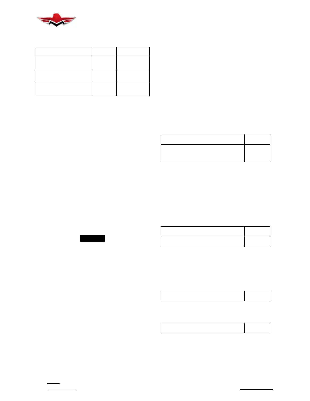
7. Post Installation. If all tests are correct to or per
steps 5 & 6, run the engine & record at 5- 10A load:
-
Values (Typ) Value
Buss voltage @
1200RPM
______V 28.2- 28.7V
Buss voltage @
1600RPM
______V 28.2- 28.7V
Buss voltage @
2000RPM
______V 28.2- 28.7V
8. If step 7 works, turn Off the engine or commence
normal operation.
24- 31- 03 - CHARGING SYSTEM MAINTENANCE
STANDBY ALTERNAT OR
1. Standby Alternator System Servicing
The B&C Model (BC410-1) alternator requires no re-
current maintenance during its service life of 1700
Hours. It is recommended that at 1700 hours or less
time in service or during engine overhaul the alternator
be overhauled. At each Annual or 100 hour inspection
required by the FAA, check the alternator externally for
security of mounting and wiring and perform the before
takeoff test described under the “Normal Procedures”
section of the Airplane Flight Manual Supplement. Fail-
ure due to broken wires or damaged connectors may
be corrected in the field using repair procedures com-
plying with the latest revision of AC43.13- xx. All other
repairs are by replacement only. B & C voltage regula-
tor (BC203- 2D) is used when installing the (BC410- 1)
standby alternator.
POST INSTALLATION TEST PROCEDURE
STANDBY ALTERNAT OR
-NOTE-
Refer to the M20V POH/AFM for specific equip-
ment limitations
1. Perform a normal engine start and allow the en-
gine to reach proper temperature for run-up RPM.
2. Assure that the standby alternator “Field” and
“Sense” circuit breakers and the “Standby Alt” master
are in the on position.
3. Reduce system electrical loads to approx. 10- 15
amps.
4. Set engine to 2000 RPM minimum.
5. Switch primary alternator field witch to OFF.
6. Check that the “Stby Alt On” G1000 annunciation
lights.
7. Increase the electrical load to over 20 amps. The
“Stby Alt On” G1000 annunciation should be blinking.
Reduce the electrical load to less than 20 Amps. The
“Stby Alt On” G1000 annunciation should be ON
steadily.
8. Reduce load and RPM.
9. Switch primary alternator field switch to ON and
verify primary alternator operation. The “Stby Alt On”
annunciator should be OFF.
10. Return the engine to idle RPM.
TROUBLESHOOTING - VOLTAGE REGULATOR
STANDBY ALTERNATOR
1. Turn all switches off. Use the lowest resistance
scale (Ω) on a DVM (Digital Volt Meter). Check resist-
ance between the battery negative (- ) terminal and
both Te rminal 7 of the regulator and the engine case.
Measurements over 0.5 Ohm to either would be cause
for investigation. In this case, check the engine ground
strap, battery ground strap, and regulator ground wire
for loose or contaminated connections, broken conduc-
tors or bad crimp joints. If these measurements are less
than 0.5 Ohm, any of these three points may be used as
reference (- ) for the following measurements.
Resistance from battery Terminal 7
______Ω
Resistance from battery to engine
case
______Ω
2. Turn on the battery master and alternator field
switches. Measure the voltage on the battery bus and
on Terminal 1 of the regulator. The voltages should be
equal within 0.2 volts. A difference of greater than 0.2
volts may be caused by using a breaker as the source
for Terminal 1 that supplies another device of consider-
able load. Change to a lightly loaded breaker or a
breaker dedicated to Terminal 1 and the low voltage
lamp. It is recommended that Terminal 1 not be jumped
to Terminal 6. If Terminal 1 has no voltage, the regulator
will not operate.
Bus Voltage
______v
Terminal 1 V oltage ______v
3. Measure the voltage on Terminal 6 of the regulator.
It should be within 0.5 volts of the bus voltage. A differ-
ence of greater than 0.5 volts may be caused by poor
contacts in the field breaker or field switch, poor crimp
joints, or loose screw terminals in the wiring between
the bus and Terminal 6. Absence of voltage on Terminal
6 will prevent the regulator from operating.
Terminal 6 V oltage
______v
4. Check the voltage on Terminal 5 of the regulator.
The voltage should be between 13 and 15 volts. A volt-
age outside this range may indicate a bad regulator.
Terminal 5 V oltage
______v
5. Move to the engine compartment. Without discon-
necting the field connector, measure the field voltage
on the alternator. Use a thin probe or small gage wire
wrapped around the probe to reach through the con-
nector body and measure the voltage on the male blade
24-31-03


 To Next Page
 Loading...