MOONEY INTERNATIONAL CORPORATION
M20V SERVICE AND MAINTENANCE MANUAL
Page
Date
20
MAR 2017
Rev Date
3. Fuel Flow System - A turbine type, fuel flow trans-
ducer is installed in the fuel line between the engine
driven fuel pump and the throttle body control of the fuel
injector system. The fuel flow is displayed on the
G1000 by electrical impulses from the transducer to in-
dicate current fuel flow at a given power setting.
24- 38- 00 - MISCELLANEOUS CIRCUITS.
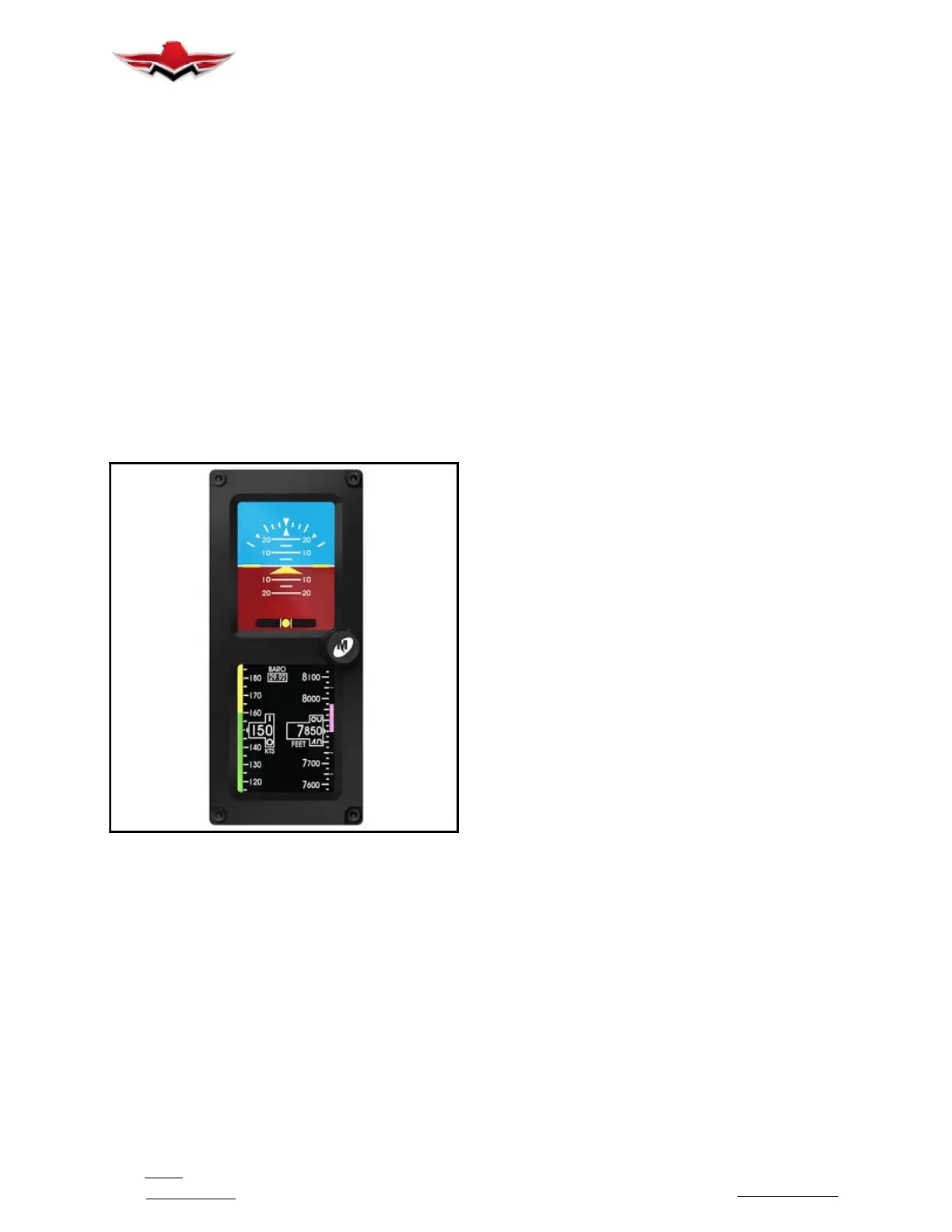
1. STANDBY ATTITUDE MODULE (SAM) - Digital
standby instrument to provide attitude, altitude, air-
speed and slip information in an advanced 2- inch
format see Figure 24- 28. In Pre- flight mode, the intro-
duction screen will be displayed for approximately five
seconds and will transition to Flight Mode when com-
plete. In Flight Mode, the unit operates normally by dis-
playing all four major functions:
Attitude, Altitude, Air-
speed and Slip Information. Heading information is
displayed if G1000 is operational. The BARO is
synced to G1000 when changed on the G1000, but
can be changed independently.
STANDBY ATTITUDE MODULE (SAM)
FIGURE 24- 28
2. GCU 275/478 KEYPAD UNIT - The GCU 275/478
refers to the Garmin Flight Management System (FMS)
Controller used in a Garmin Integrated Flight Deck. The
GCU 478 Line Replaceable Unit (LRU) provides alpha-
numeric, softkey, and flight planning function keys used
to interface with a Garmin Integrated Flight Deck. In ad-
dition to alphanumeric, softkey, and flight planning
function keys the GCU 478 provides COM/NAV tuning
capabilities. The GCU 478 also provides heading,
course, and altitude controls. The GCU 478 mounts
flush to the aircraft instrument panel using four
turn
fasteners. The GCU 275 provides flight planning func-
tions and COM/NAV tuning capabilities. The GCU 275
mounts flush to the aircraft instrument panel using four
captive screws.
3. Heated Pitot Tube - A switch controls the pitot tube
heater.
4. Hour Meter -
Hour meter - located on baggage
compartment bulkhead indicates actual flight time
and is triggered by the G1000 airspeed indication
setting. Location may vary depending on installed
systems.
5. Accessory USB Socket. A 5 volt accessory dual
USB is mounted in the lower right instrument panel and
in between rear passenger seats.
6. Emergency Lighting - A circuit will allow standby
instruments to energize and illuminate when emergen-
cy lighting is in use.
7. Ice Light (if equipped) - Lighting to alert the pilot of
ice formation on surfaces of an aircraft.
24-38-00
 Loading...


