MOONEY INTERNATIONAL CORPORATION
M20V SERVICE AND MAINTENANCE MANUAL
Page
Date
8
MAR 2017
Rev Date
The crash sensor’s predetermined deployment thresh-
old does not allow inadvertent deployment during nor-
mal operations, such as hard landings, vibration, or tur-
bulence.
To activate the system, join (buckle) the three- point re-
straint in the same manner as any other three- point
seatbelt. Unbuckling the seatbelt safes the AAIR Sys-
tem.
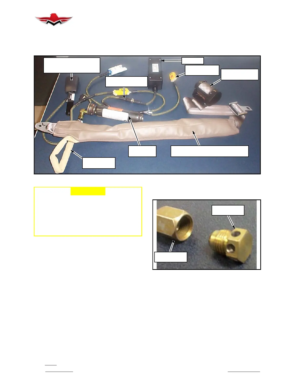
END- RELEASE BUCKLE
ASSEMBLY
(20A,20B,20C,20D)
EMA (50)
CONNECTOR
FOR 2ND SEAT
INERTIA REEL
(FOR 10A & 10B)
THREE- POINT AIRBAG BELT
(10A, 10B, 10C & 10D NOT SHOWN)
INFLATOR
ASSEMBLY
AIRBAG BELT
HOSE
CABLE INTERFACE
ASSEMBLY
AAIR V23 SYSTEM COMPONENTS
FIGURE 25- 1
-CAUTION-
The Inflatable Airbag Restraint System is “live”
when all connections are made and the buckle
is connected.
The Inflatable Airbag Restraint System Inflator
is a stored gas/energetic device. Severe per-
sonal injury may be caused by misuse or tam-
pering
Refer to AMSAFE AAIR Supplemental Maintenance
Manual E508923( ) for system handling and connectiv-
ity.
Refer to Standard Restraint System steps above for re-
moving restraints from cabin anchor points.
AAIR V23 SYSTEM COMPONENTS AND PARTS
The AAIR V23 System consists of these core compo-
nents:
S Seatbelt Airbag Assembly (SAA)
S Inflator Assembly
S Electronics Module Assembly (EMA)
S Cable Interface Assembly
The SAA (1A, 1B, 1C, 1D) consists of two primary sub-
assemblies; the Three- Point Airbag Belt Assy (10A,
10B, 10C, 10D) with Safety Cable Tie and the End- Re-
lease Buckle Assy (20A, 20B, 20C, 20D) (see Figure
25- 1). The SAA mounts to seat and aircraft structure
using existing mounting points. The End- Release
Buckle Assy provides the electrical connector to the In-
flator Assy and the Cable Interface Assy (40A, 40B).
INFLATOR
SHIPPING CAP
INFLATOR
HOSE FITTING
INFLATOR SHIPPING CAP
FIGURE 25- 2
The Inflator Assembly (Figure 25- 2) mounts under the
pilot and co- pilot seats, and in the sidewall for the rear
seats. The Inflator Shipping Cap makes the inflator a
thrust- neutral device and is to be used whenever the
inflator is shipped as a non- installed item. The Cable
Interface Assy connects the EMA (50) to two SAAs and
also provides a Diagnostic Tool Connector leg (see Fig-
ure 25- 1). The Diagnostic Tool Connector connects to
the System Diagnostic Tool to facilitate system func-
tional checks. The EMA, which contains the system
electronics and system power (Lithium- type battery),
is mounted to aircraft structure under the rear seats.
25-10-03
 Loading...


