MOONEY INTERNATIONAL CORPORATION
M20V SERVICE AND MAINTENANCE MANUAL
Page
Date
6
MAR 2017
Rev Date
(2) When system pressure is obtained, the
“Anti- Ice” LED should extinguish and the “De- Ice LED
should show steady GREEN.
(3) Repeat procedure with both metering
pumps.
B. Switch OFF for sufficient time for system pres-
sure to fall (approximately 2 minutes).
C. Select “Anti- Ice”.
(1) The “Anti- Ice” LED should flash alternating
RED/GREEN and the ”De- Ice” LED should flash RED/
OFF as system pressure rises (approximately 20
seconds).
(2) When system pressure is obtained, the ”De-
Ice” LED should extinguish and the “Anti- Ice” LED
should show steady GREEN.
(3) Repeat procedure with both metering
pumps.
4. Operate Windshield Spray bar on each windshield
pump to ensure proper operation and absence of
leaks.
5. Filter is located at baggage floor stiffener. Inspect
system filter and replace as needed.
A. The “high pressure” LED will illuminate YEL-
LOW if the filter element requires replacing. It should
NOT illuminate during testing but may be tripped ON
occasionally during aircraft electrical system switching
or during engine start. Cancel by depressing “Reset”
switch (use ball point pen tip or similar device).
B. Test “High Pressure” LED by depressing “Re-
set” switch. YELLOW LED should illuminate while
switch is depressed, but go OFF when “Reset” is
released.
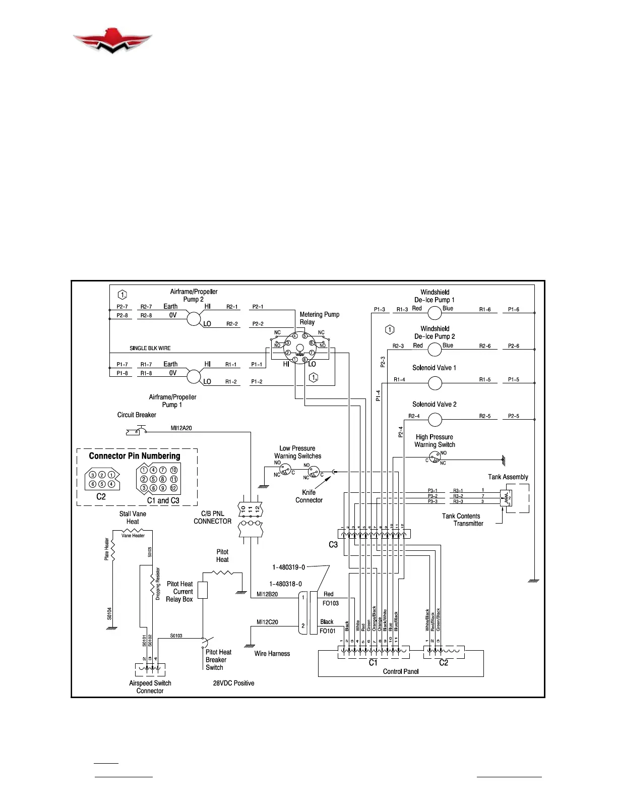
5. See typical ice protection system schematic on
next pages.
AIRFRAME ICE PROTECTION ELECTRICAL SCHEMATIC
FIGURE 30-1
30-12-00


 To Next Page