MOONEY INTERNATIONAL CORPORATION
M20V SERVICE AND MAINTENANCE MANUAL
Page
Date
15
MAR 2017
Rev Date
2.7
2.9
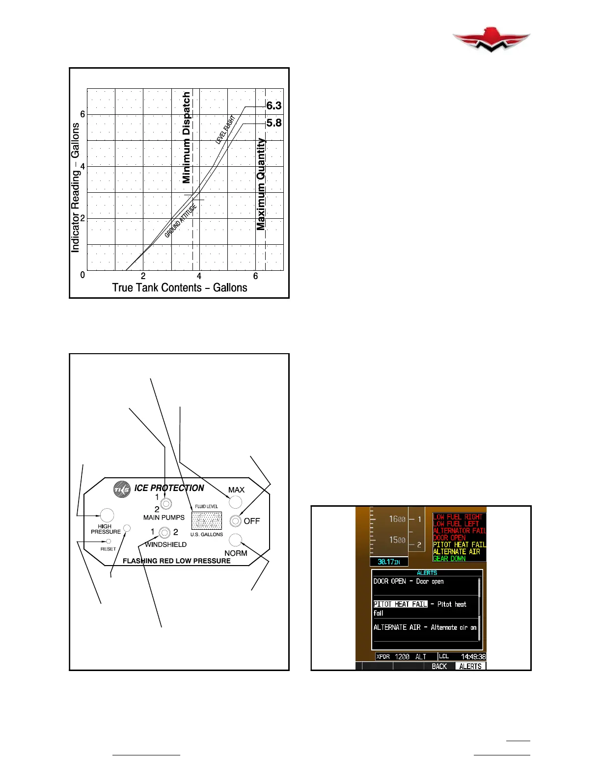
FLUID INDICATOR CALIBRATION
FIGURE 30-3
Calibration
Pot
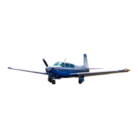
High Pressure Warning
Cancel Switch (recessed)
Depress with ball pen
or pencil point
Windshield Pump Switch
Left
Center
Right
-Pump1ON
-OFF
-Pump2ON
Indicator Lamp (green/red)
Green
Red (flashing)
- NORMAL flow selected
- low pressure warning
Main Pump Mode Select Switch
Up
Center
Down
- MAXIMUM (max flow rate)
-OFF
- NORMAL (normal flow rate)
Indicator Lamp (green/red)
Green
Red
- MAXIMUM flow selected
- low pressure warning
Tank Contents Indication
Digital display of fluid
remainingingallonsandtenths
Main Pump Select Switch
UP
DOWN
-Pump1
-Pump2
Indicator Lamp (amber)
High pressure warning
when ON indicates the
need to replace filter element
TKS CONTROL HEAD
FIGURE 30-4
30-12-03 - FLUID LEVEL CALIBRATION
To adjust fluid level reading at A/C instrument panel
TKS Control Head:
1. Level aircraft to flight level attitude.
2. Switch electrical power ON.
3. Locate TKS fluid filler tube accessible through ac-
cess panel on right side aft fuselage.
4. Fill fluid tank to just at overflow with approved de-
icing fluid. This level of fill tops off reservoirs to hold 6.3
gallons of fluid (unusable volume of fluid is 0.10 gallon =
6.3 gallons).
5. Locate TKS adjusting POT on left center portion of
TKS control head (see Figure 30- 4). Adjust POT with
screwdriver until “6.2” is indicated on Fluid Level Indi-
cator (unusable volume of fluid is 0.10 gallon = 6.3 gal-
lons).
6. Remove any spilled de- icing fluid per instructions
in Section 30-11-01.
7. Turn aircraft power OFF.
8. Place aircraft on ground.
30-30-00 - PITOT - DESCRIPTION AND OPERA-
TION
A standard heated pitot tube is located on left wing at
Wing Station No. 145. The pitot heat switch/circuit
breaker, located on lower left instrument panel, sup-
plies power to the pitot tube heating element. If system
is operating properly, the GREEN Pitot Heat switch
lamp is illuminated, and the G1000 shows no annunci-
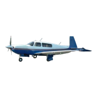
ation. When AMBER PITOT HEAT is illuminated, and
the PITOT HEAT switch is in ON position (Green PITOT
HEAT switch lamp illuminated), the Pitot Heat system
has failed (see Figure 30- 5). When the optional TKS
System for flight into known icing conditions is installed,
the heated Pitot tube is a part of the TKS system.
PITOT HEAT FAIL - G1000 ANNUNCIATION
FIGURE 30-5
30-12-03


 To Next Page