MOONEY INTERNATIONAL CORPORATION
M20V SERVICE AND MAINTENANCE MANUAL
Date
MAR 2017
Rev Date
Page
7
4. Re- install headliner panel; secure with two (2)
screws.
60620-1
(2 QTY)
60620-1
(3 QTY)
60619-1
(2 QTY)
SOCKET
PIN
PIN
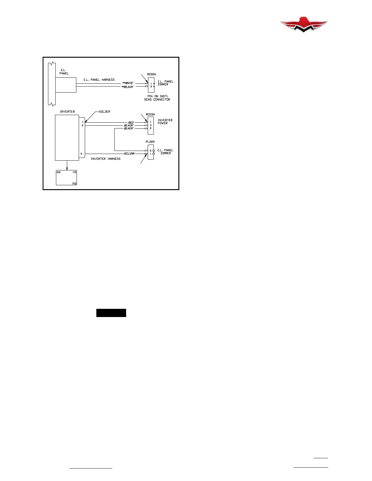
E.L. PANEL TO INVERTER SCHEMATIC
FIGURE 33- 2
33-20-00 - INTERIOR LIGHTS - MAINTENANCE
PRACTICES
33-21-00 - CABIN LIGHTS - OVERHEAD LIGHTS/
BULB REPLACEMENT
1. Carefully slide smooth, flat sharp blade under lip of
light assembly flange and pop light assembly out of
mounting hole (Figure 33- 1).
2. Disconnect blade terminals from light assembly.
3. Hold light assembly body and rotate bulb holder
counterclockwise to remove.
4. Pull bulb from bulb holder and replace with new
bulb. Reinstall bulb holder.
5. Re- assemble light assembly into mounting hole.
6. Check for proper operation.
-NOTE-
The front and rear light bulbs are replaced in the
same manner.
33-21-01 - CABIN LIGHT SWITCH
REPLACEMENTS
FRONT & REAR SEAT PASSENGER’S
SWITCHES.
1. Carefully slide smooth, flat sharp blade under lip of
light assembly flange and pop light assembly out of
mounting hole (Figure 33- 1).
2. Switches are a snap fit and may be removed by
pressing snap tabs and pushing switch through cover.
3. Disconnect wire terminals and replace with new
switch. Check for proper operation.
4. Reassemble switch assembly into mounting hole.
BAGGAGE COMPARTMENT SWITCH
1. Switch is located at rear of baggage door at front,
top of hat rack opening. (Figure 33- 1)
2. Remove one screw inboard of switch on door
frame trim. Pull door frame down slightly from Velcro
fasteners to access baggage compartment light switch.
3. Press snap tabs and PUSH switch through panel.
4. Disconnect terminals; replace switch.
5. Re- assemble in reverse order.
33-22-00 - INSTRUMENT/FLIGHT PANEL AND
GLARESHIELD LIGHTS
33-22-01 - LIGHT BULB REPLACEMENT
1. Instrument panel lights.
A. Internally lighted instruments are not being con-
sidered in this information.
B. Post light bulbs are replaced by pulling hood
straight out from post light base and then pulling bulb
from this hooded portion.
C. Insert new bulb into hood and push hood back
onto post light base.
D. Check for proper operation and hood orienta-
tion.
2. Glareshield lights.
A. Remove outer housing by unscrewing from light
assembly base.
B. Remove bulb; insert new bulb.
C. Screw outer housing back onto base.
D. Check for proper operation.
3. Map Light (LED)
A. Remove two (2) screws securing Map Light As-
sembly to control wheel (ref. Fig. 33- 3).
B. Remove three (3) screws securing back cover
containing Map Light Dimmer Knob and POT assem-
blies.
C. Pull Back Cover, with Knob/POT assemblies,
away from control wheel to expose Map Light pigtail.
Disconnect pigtail from POT.
D. Replace Map Light Assembly.
E. Reassemble in reverse order and check for
proper operation.
33-20-00
 Loading...


