MOONEY INTERNATIONAL CORPORATION
M20V SERVICE AND MAINTENANCE MANUAL
Date
MAR 2017
Rev Date
Page
17
pack. The register records activation time in 30 second
increments so all activations will count as at least 30
seconds, even if actual time is much less. Total allow-
able time is 60 minutes as determined by FAR 91.207
and RTCA DO- 204. After this time has been accumu-
lated, a 7 flash error will be presented after the self-
test. The battery must be replaced at this point for the
ELT to remain in compliance.
Once all tests have been satisfactorily completed and
all harness connections have been verified to be cor-
rect, the connectors at the remote cockpit switch and
the ELT should be sealed to prevent moisture from get-
ting into the wire entry holes.
Seal using an electronics grade (neutral cure) non-
slumping RTV such as GE Silicone RTV162, Dow
Corning 748RTV or Silastic 1080RTV. These are com-
monly available at pet stores which sell aquariums.
Apply RTV to the rear of the 9- pin connector remote
switch (Artex P/N 151- 5009), forcing the sealant into
wire holes and around exposed wire ends.
Disassemble the harness D- sub connector and cover
exposed wire ends and all connectors pins with RTV.
Coat all exposed metal, taking care to keep away from
the thumb screws. Reassemble after sealing.
BATTERY REPLACEMENT - ARTEX ME-406
Remove ELT
Remove the ELT from its mounting tray. Inspect the
mounting hardware. Ensure the hardware is free of
cracks or other obvious damage Battery removal.
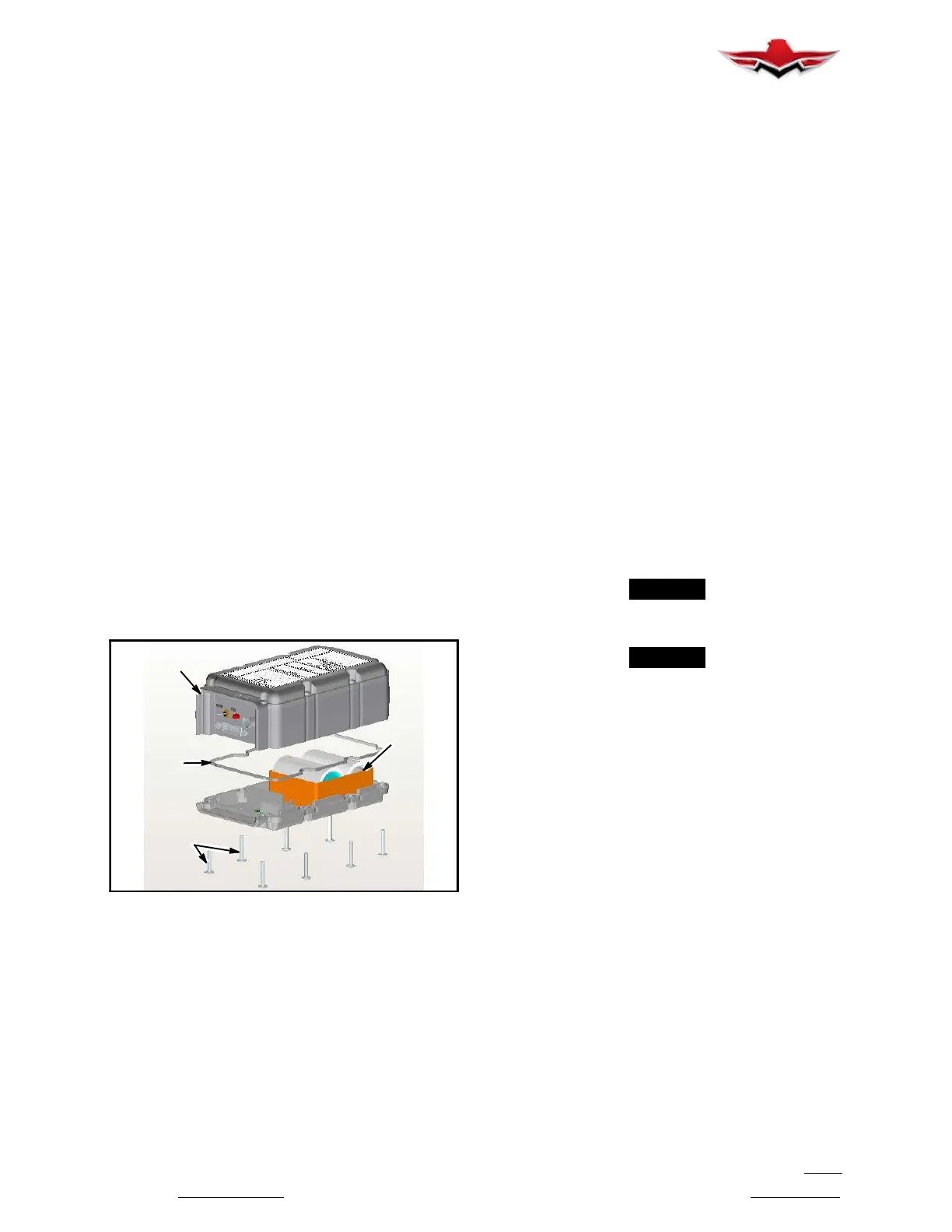
SCREWS
COVER
BATTERY
PACK
MOUNTING
GASKET
BATTERY REPLACEMENT (ELT - ARTEX ME- 406)
FIGURE 39-13
NOTE:
The battery pack contains static sensitive parts,
take ESD precautions before handling.
Remove the (8) securing screws from the battery-side
cover (Figure 39- 13). Battery pack is identified by the
embossed text: “BATTERY ACCESS ON THIS SIDE”.
Carefully lift the battery cover (battery pack) away from
the ELT and unplug the flex- cable connected to the
pack. Do not pull on the flexible portion of the cable -
use the rigid section of the flex circuit at the connector
as a handle. Inspect the battery pack and ELT chassis.
The battery cells, components and connectors should
be free of corrosion. Inspect flex- circuit for broken con-
nections or damage. Ensure the battery housing is free
of cracks or other visible damage. Verify the battery ex-
piration date. If the battery pack has not expired it may
be reinstalled. The battery pack must be replaced with
a new one:
After use in an emergency.
When the transmitter has been in use for more than 1
cumulative hour; (7 flash error).
After an inadvertent activation of unknown duration.
On or before the battery replacement (expiration) date
Battery pack replacement.
If replacing the battery pack, order replacement kit
455- 0012 which contains the battery pack (452- 6499)
(ME406 Series LiMnO2 Battery Pack), replacement
gasket, hardware and labels (for Log Book and Battery
Pack). Lay the battery pack on the work surface with
the batteries facing up. Install a replacement seal in the
slot along the perimeter of the housing. Leaving the
battery as it is, position the ELT over the battery pack
with one hand and plug the flex- cable connector into
the battery assembly using the other. The cable should
not be twisted and the connector should “click” into
place.
-NOTE-
The battery connector is keyed to prevent
incorrect installation.
-NOTE-
Mate the ELT to the battery, making sure that the
seal is positioned correctly during the process.
Replace the 8 securing screws and torque to
10-12 inch- lbs. Enter pertinent battery replace-
mentinformationintheaircraftlogbookandfill
out any other documentation required by local
authority.
Refer to Artex “Description, Operation, Installation and
Maintenance Manual for ME406 ELT” for detailed
Maintenance and Troubleshooting information.
39-20-00 - ELECTRICAL/ELECTRONIC EQUIP-
MENT RACK
The electrical equipment rack for the M20V aircraft is
located in tailcone just aft of baggage compartment
bulkhead. Access is gained through large access door
in tailcone aft of left wing trailing edge. The batteries,
auxiliary power plug receptacle (if installed), and vari-
ous avionics black boxes are mounted on electrical
equipment rack. The ELT is mounted on an accessory
rack further aft in tailcone.
39-21-00 - MISCELLANEOUS MAINTENANCE
39-21-01 - EQUIPMENT MAINTENANCE
Refer to SECTION 27- 42- 00 for Electric Trim Sys
tem
Maintenance.
39-20-00
 Loading...


