MOONEY INTERNATIONAL CORPORATION
M20V SERVICE AND MAINTENANCE MANUAL
Date
MAR 2017
Rev Date
Page
9
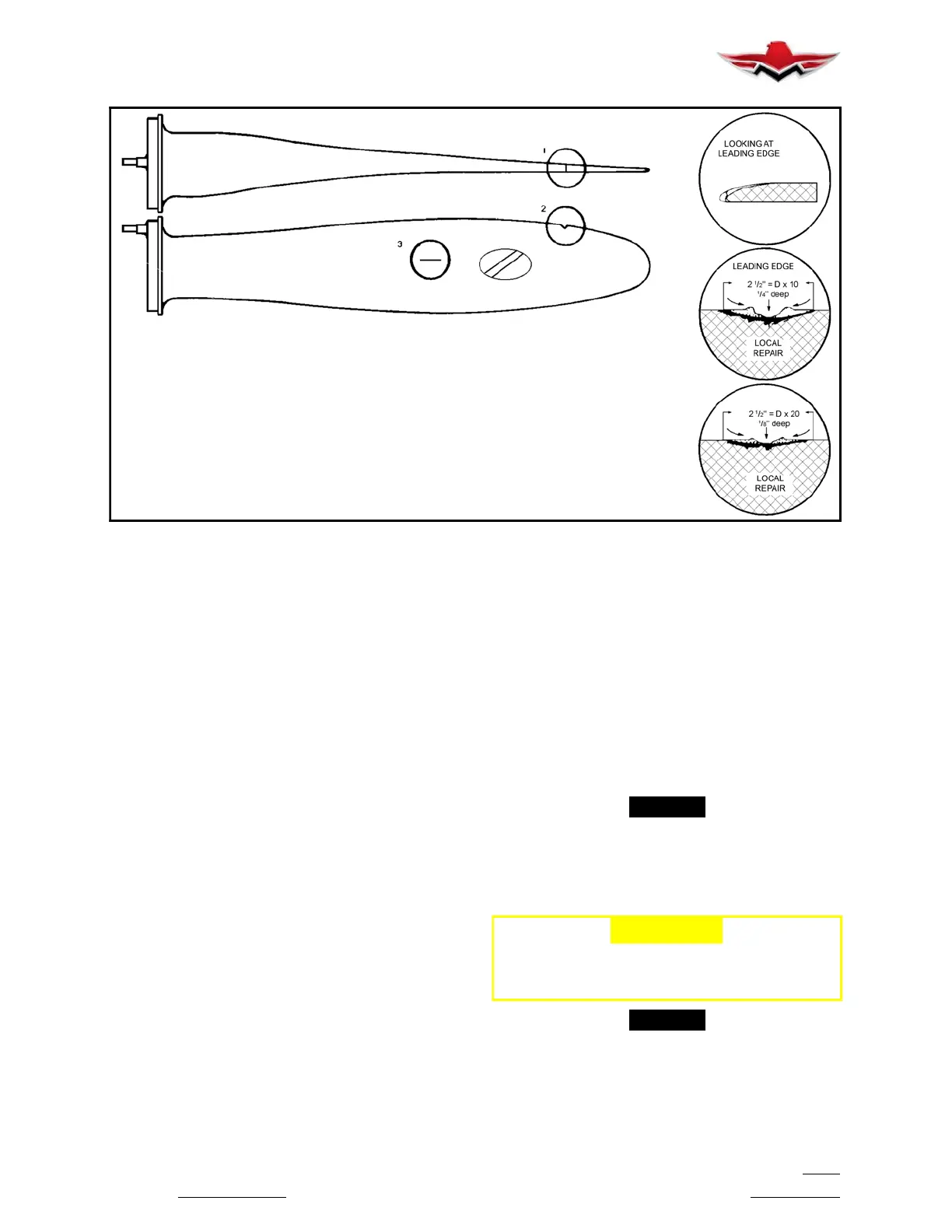
1
2
3
To determine amount of rework needed, use the following formula:
On the leading and trailing edge of the blade, measure the depth of the damage,
and multiply this number x 10 (see Example 2, above). Rework the area surrounding
the damage 10 times the depth of the damage.
Onthefaceandcamberof the blade, measure the depth of the damage, and
multiply this number x 20 (see Example 3, above). Rework the area surrounding the
damage 20 times the depth of the damage
.
PROPELLER BLADE MINOR REPAIRS
FIGURE 61- 5
61-10-10 - MINOR PROPELLER BLADE REPAIR
1. Minor nicks, dents and gouges may be dressed out
by approved personnel and propeller manufacturer’s
recommendations. Nicks, gouges, and scratches on
blade surfaces or on the leading or trailing edges of the
blade, greater than 1/32 inch wide or deep, must be re-
moved before flight. Field repair of small nicks and
scratches may be performed by qualified personnel in
accordance with FAA Advisory Circular 43.13- 1B, as
well as the procedures specified below. Normal blade
lead edge erosion (sand- blasted appearance) is ac-
ceptable, and does not require removal before further
flight.
2. Local repairs may be made using files, electrical or
air powered equipment. Emery cloth, Scotch Brite,
and crocus cloth are to be used for final finishing. Refer
to (Figure 61- 5).
3. Repaint area per propeller manufacturer’s recom-
mendations to reduce corrosive action.
61-20-00 - PROPELLER CONTROLLING
61-20-10 - PROPELLER GOVERNOR CONTROL
RIGGING
1. Disconnect propeller governor control rod.
A. Remove cotter pin, nut, bolt and washers from
rod end at propeller governor control arm.
B. Disconnect control rod from governor control
arm.
2. Adjust control arm spring to minimum tension
which will return control arm to maximum RPM.
3. Push propeller control in cockpit, full forward. Pull
control back approximately 1/8 inch and lock in this
position.
4. Place governor control arm against high RPM stop
screw.
5. Adjust propeller control rod end to coincide with
governor arm position.
6. Attach control rod end to governor arm and replace
cotter pin.
7. Operate propeller control from cockpit to verify full
travel of control arm in both directions, high RPM to
minimum RPM stop.
-NOTE-
When propeller control rigging is complete,
check controls in cockpit to be sure there is 1/8
inch cushion between control knob and adjust-
ment nut on instrument panel. The control
should not bottom out when pushed full forward.
-CAUTION-
Recheck safety wire, security and thread
engagement on all engine controls after
adjustment, rigging or assembly.
-NOTE-
Vernier control’s friction can be adjusted by loos-
ening lock nut on back side of panel and either
tighten nut on front of panel to increase friction
or loosen nut to decrease friction. Retighten lock
nut on back side to secure cable to panel.
61-10-10
 Loading...


