MOONEY INTERNATIONAL CORPORATION
M20V SERVICE AND MAINTENANCE MANUAL
Date
MAR 2017
Rev Date
Page
5
78-00-00 - GENERAL
The exhaust system’s headers, turbochargers and ex-
haust pipes are manufactured by Continental Motors
Incorporated (CMI). They are designed to optimally
scavenge the cylinders exhaust gases during normal
engine operation. Refer to CMI Service and Mainte-
nance Manual M18 for more detailed information on re-
moval and installation of the exhaust system.
Inspections for cracks, burns, etc. are required during
each maintenance activity and recommended before
each flight.
78-10-00 - EXHAUST SYSTEM INSTALLATION
1. EXHAUST PIPE HEADERS TO ENGINE.
A. Place new exhaust gaskets in position on the LH
& RH engine exhaust flange studs.
B. Place either LH or RH header pipe into position
on engine cylinder exhaust flanges. Be careful during
this procedure to ensure that the exhaust gaskets re-
main in proper position on each cylinder exhaust
flange.
-NOTE-
Attach new headers with existing exhaust flange
stud nuts. (If nuts have been damaged, replace
them with new nuts
(available from Continental Motors).
Leave exhaust flange stud nuts loose so header is
movable.
C. Lubricate outside of inner and inside of all outer
slip joints on headers and the outside of header pipe
flanges with MIL-A-907 type Hi- temp anti- seize com-
pound, C5-A (Fel- Pro) or equivalent.
2. EXHAUST SYSTEM REMOVAL
Refer to Chapter 71-00-10 Engine Removal instruc-
tions for turbocharger/exhaust sys
tem connections
and refer to Fig. 78-2.
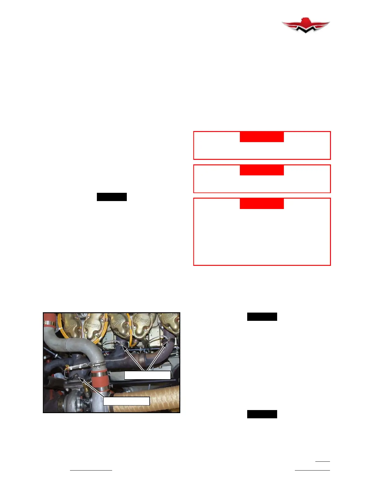
EGT PROBES
TIT PROBE
EGT/TIT INSTALLATION (TYP)
FIGURE 78- 1
3. EGT PROBE INSTALLATION/SECURITY
Garmin G1000 equipped M20V aircraft utilize six cylin-
der EGT probes and one system TIT probe to monitor
exhaust gas temperatures. Refer to Probe manufac-
turer’s service literature for recommended mainten-
ance and troubleshooting.
78-30-00 - EXHAUST SYSTEM SERVICING
1. CLEANING
To properly inspect exhaust system, components must
be clean and free of oil, grease, etc. Clean as follows:
A. Spray engine exhaust system components with
a suitable solvent (Stoddard Solvent), allow to drain
and wipe dry with clean cloth.
-WARNING-
When using Stoddard Solvent, follow direc-
tions and warnings given by the manufacturer.
-WARNING-
Never use highly flammable solvents on en-
gine exhaust systems.
-WARNING-
Never use a wire brush or abrasives to clean
exhaust systems or mark on system with lead
pencils. A mark with pencil lead (zinc or gal-
vanized tool) can be absorbed by the metal of
the exhaust system when heated. This
causes a change in its molecular structure.
This softens the metal in the area of the mark,
and can cause cracks and eventual failure.
2. VISUAL INSPECTION OF COMPLETE SYSTEM
A thorough inspection of engine exhaust system will
detect any breaks or cracks causing leaks which might
result in loss of efficiency, loss of engine power or en-
gine compartment fire. Inspect per following proce-
dures:
-NOTE-
This inspection should be conducted when
engine is cool.
A. LOOK FOR LEAKS - Examine surfaces adja-
cent to exhaust system components for signs of ex-
haust soot. Look for gray, red or black gas stains at
welds, clamps, flanges, etc. Inspect exhaust system for
chaffing by cowling, engine mount, cables or any air-
frame components.
Inspect exhaust stacks for burned areas, cracks and
looseness.
B. LOOSE CONNECTIONS - Inspect exhaust
clamps for cracks, looseness and proper security.
-NOTE-
During inspection, particular attention should be
given to condition and security of flanges, spot
welds, slip joints, and welded areas.
78-00-00
 Loading...


